MKP18394075632R 查看數據表(PDF) - Vishay Semiconductors
零件编号
产品描述 (功能)
比赛名单
MKP18394075632R
Vishay Semiconductors

MKP18394075632R Datasheet PDF : 12 Pages
| |||
www.vishay.com
MKP1839
Vishay Roederstein
POWER DISSIPATION AND MAXIMUM COMPONENT TEMPERATURE RISE
The power dissipation must be limited in order not to exceed the maximum allowed component temperature rise as a function
of the free air ambient temperature.
The power dissipation can be calculated according type detail specification “HQN-384-01/101: Technical Information Film
Capacitors with the typical tgd of the curves”.
The component temperature rise (T) can be measured (see section “Measuring the component temperature” for more details)
or calculated by T = P/G:
• T = Component temperature rise (°C)
• P = Power dissipation of the component (mW)
• G = Heat conductivity of the component (mW/°C)
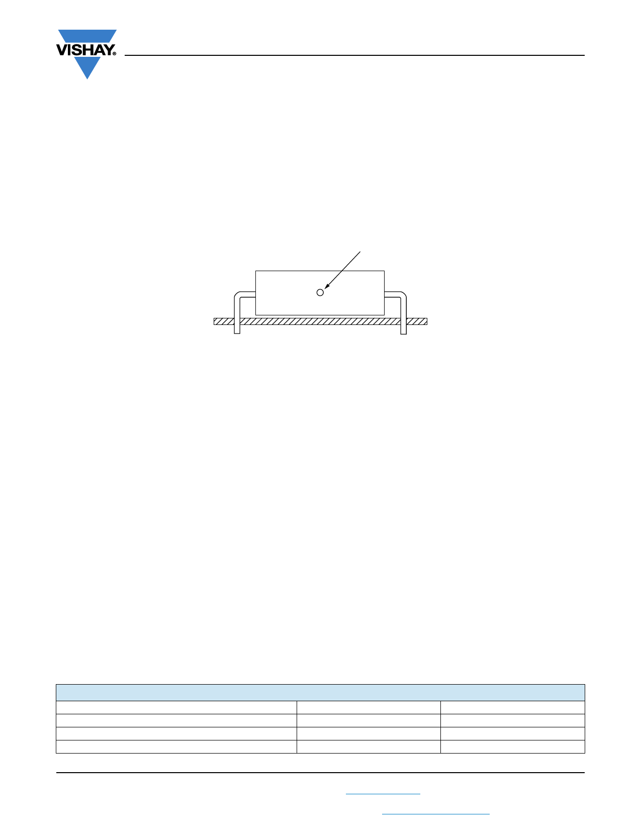
MEASURING THE COMPONENT TEMPERATURE
A thermocouple must be attached to the capacitor body as in:
Thermocouple
The temperature is measured in unloaded (Tamb) and maximum loaded condition (TC).
The temperature rise is given by T = TC - Tamb.
To avoid radiation or convection, the capacitor should be tested in a wind-free box.
APPLICATION NOTE AND LIMITING CONDITIONS
These capacitors are not suitable for mains applications as across-the-line capacitors without additional protection, as
described hereunder. These mains applications are strictly regulated in safety standards and therefore electromagnetic
interference suppression capacitors conforming the standards must be used.
To select the capacitor for a certain application, the following conditions must be checked:
1. The peak voltage (UP) shall not be greater than the rated DC voltage (URDC)
2. The peak-to-peak voltage (UP-P) shall not be greater than the maximum (UP-P) to avoid the ionization inception level
3. The voltage peak slope (dU/dt) shall not exceed the rated voltage pulse slope in an RC-circuit at rated voltage and without
ringing. If the pulse voltage is lower than the rated DC voltage, the rated voltage pulse slope may be multiplied by URDC and
divided by the applied voltage.
For all other pulses following equation must be fulfilled:
2
x
T
d--d--U-t--
2
x
dt
URDC
d--d--U--t-
rated
0
T is the pulse duration.
4. The maximum component surface temperature rise must be lower than the limits (see graph “Max. allowed component
temperature rise”).
5. Since in circuits used at voltages over 280 V peak-to-peak the risk for an intrinsically active flammability after a capacitor
breakdown (short circuit) increases, it is recommended that the power to the component is limited to 100 times the values
mentioned in the table: “Heat conductivity”
6. When using these capacitors as across-the-line capacitor in the input filter for mains applications or as series connected
with an impedance to the mains the applicant must guarantee that the following conditions are fulfilled in any case (spikes
and surge voltages from the mains included).
VOLTAGE CONDITIONS FOR 6 ABOVE
ALLOWED VOLTAGES
Maximum continuous RMS voltage
Maximum temperature RMS-overvoltage (< 24 h)
Maximum peak voltage (VO-P) (< 2 s)
Tamb 85 °C
URAC
1.25 x URAC
1.6 x URDC
85 °C < Tamb 100 °C
URAC
1.25 x URAC
1.1 x URDC
Revision: 10-Dec-13
8
Document Number: 26022
For technical questions, contact: dc-film@vishay.com
THIS DOCUMENT IS SUBJECT TO CHANGE WITHOUT NOTICE. THE PRODUCTS DESCRIBED HEREIN AND THIS DOCUMENT
ARE SUBJECT TO SPECIFIC DISCLAIMERS, SET FORTH AT www.vishay.com/doc?91000
Share Link: