BFC246743223 查看數據表(PDF) - Vishay Semiconductors
零件编号
产品描述 (功能)
比赛名单
BFC246743223 Datasheet PDF : 22 Pages
| |||
www.vishay.com
MKT467, MKT468
Vishay BCcomponents
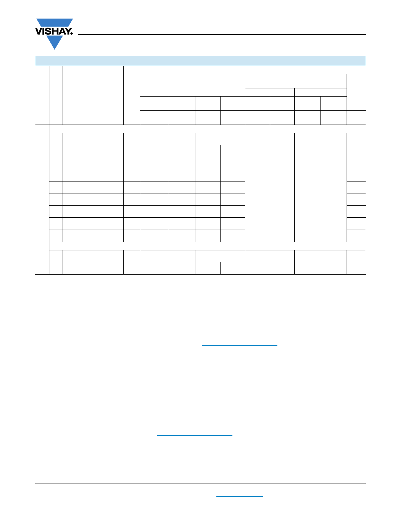
ELECTRICAL DATA AND ORDERING INFORMATION: MKT468
CATALOG NUMBER BFC2 468 XXYYY AND PACKAGING
URDC CAP.
(V) (μF)
DIMENSIONS
wmax. x h (h’)max. x lmax.
(mm)
MASS
(g) (1)
C-TOL. =
± 10 %
REEL
LOOSE IN BOX
H = 16.0 mm
ORIGINAL PITCH
BENT BACK PITCH
C-
VALUE
C-TOL. = C-TOL. = C-TOL. = C-TOL. = C-TOL. = C-TOL. = C-TOL. =
± 5 % ± 10 % ± 5 % ± 10 % ± 5 % ± 10 % ± 5 %
XX
(SPQ)
XX
(SPQ)
XX
(SPQ)
XX
(SPQ)
XX
(SPQ)
XX
(SPQ)
XX
(SPQ)
XX
(SPQ)
..YYY
Pitch = 22.5 mm ± 0.4 mm; dt = 0.80 mm ± 0.08 mm (URAC = 250 V)
0.18 7.5 x 19.5 x 26.0
lt = 3.5 mm
± 0.5 mm
2.5
40...
(1000)
41...
(1000)
lt = 25.0 mm
± 4.0 mm
57...
(650)
58...
(650)
P = 22.5 mm
P0 = 12.7 mm
P = 7.5 mm
P0 = 15.0 mm
184
0.22 8.0 x 21.0 x 26.0
2.8
40...
(750)
41...
(750)
57...
(500)
58...
(500)
224
0.27 9.0 x 22.0 x 26.0
3.3
40...
(750)
41...
(750)
57...
(500)
58...
(500)
274
0.33
630 0.39
10.0 x 23.0 x 26.0
11.5 x 24.0 x 26.0
3.5
40...
(700)
4.2
40...
(600)
41...
(700)
41...
(600)
57...
(450)
57...
(400)
58...
(450)
58...
(400)
-
334
-
394
0.47 12.5 x 25.5 x 26.0
4.5
40...
(500)
41...
(500)
57...
(300)
58...
(300)
474
0.56 13.5 x 26.6 x 26.0
5.5
40...
(450)
41...
(450)
57...
(300)
58...
(300)
564
0.68 15.0 x 28.0 x 26.0
6.5
40...
(400)
41...
(400)
57...
(250)
58...
(250)
684
Pitch = 27.5 mm ± 0.4 mm; dt = 0.80 mm ± 0.08 mm; A = 2.5 mm + 1.4 mm / - 0.5 mm (URAC = 250 V)
lt = 3.5 mm
± 0.5 mm
lt = 24.0 mm
± 4.0 mm
P = 27.5 mm
P0 = 12.7 mm
P = 7.5 mm
P0 = 15.0 mm
0.82 15.0 x 28.0 x 30.0
7.5
40...
(300)
41...
(300)
57...
(200)
58...
(200)
-
-
-
Notes
• SPQ = Standard Packing Quantity
(1) Net weight for short lead product only
MOUNTING
Normal Use
The capacitors are designed for mounting on printed-circuit boards. The capacitors packed in bandoliers are designed for
mounting in printed-circuit boards by means of automatic insertion machines.
For detailed tape specifications refer to packaging information: www.vishay.com/doc?28139
Specific Method of Mounting to Withstand Vibration and Shock
In order to withstand vibration and shock tests, it must be ensured that the underside and the kinks are in good contact with
the printed-circuit board.
• For pitches 15 mm capacitors shall be mechanically fixed by the leads
• For larger pitches the capacitors shall be mounted in the same way and the body clamped
Storage Temperature
Tstg = -25 °C to +35 °C with RH maximum 75 % without condensation
SOLDERING
For general soldering conditions and wave soldering profile, we refer to the application note:
“Soldering Guidelines for Film Capacitors”: www.vishay.com/doc?28171
Ratings and Characteristics Reference Conditions
Unless otherwise specified, all electrical values apply to an ambient free air temperature of 23 °C ± 1 °C, an atmospheric
pressure of 86 kPa to 106 kPa and a relative humidity of 50 % ± 2 %.
For reference testing, a conditioning period shall be applied over 96 h ± 4 h by heating the products in a circulating air oven at
the rated temperature and a relative humidity not exceeding 20 %.
Revision: 27-Mar-18
10
Document Number: 28105
For technical questions, contact: dc-film@vishay.com
THIS DOCUMENT IS SUBJECT TO CHANGE WITHOUT NOTICE. THE PRODUCTS DESCRIBED HEREIN AND THIS DOCUMENT
ARE SUBJECT TO SPECIFIC DISCLAIMERS, SET FORTH AT www.vishay.com/doc?91000
Share Link: 