GS9023 查看數據表(PDF) - Gennum -> Semtech
零件编号
产品描述 (功能)
比赛名单
GS9023 Datasheet PDF : 33 Pages
| |||
Video Data Output
The video signal is output at the DOUT[9:0] pins. The video
signal is synchronized to the rising edge of PCLK. When the
GS9023 is properly configured, audio packets, extended
audio packets, audio control packets and arbitrary data
packets are multiplexed into the output video signal. When
the video signal is a 525 line or 625 line D2 format, TRS
information is added to the video signal if the TRS input pin
or the “D2_TRS” and “VSEL” bits of Host Interface Register
#0h are HIGH. EDH packets can also be inserted into the
video signal by setting the EDH_INS pin HIGH or by setting
the “EDHON” bit HIGH of Host Interface Register #1h.
When selected, the GS9023 inserts EDH packets according
to SMPTE RP165.
NOTE: Active picture and full field data words are updated
from recalculated values but error flag information is
replaced with the values programmed in Host Interface
Registers #Eh and #Fh.
NOTE: In the 525/4:4:4:4 video standard, EDH packets
should not be inserted as this can lead to TRS signal
corruption. When EDH packets are not inserted, the
“EDHDEL” bit of Host Interface Register #0h controls the
deletion of EDH packets. When the “EDHDEL” bit is set
LOW, EDH packets are deleted from the incoming video
signal. When “EDHDEL” is set HIGH, EDH packets pass
through the device unchanged.
NOTE: “EDHDEL” functionality is valid only when the
“CASCADE” bit of Host Interface Register #4h is LOW.
Audio Clock Input
A master audio clock (128 fs: 6.144MHz) must be supplied
to the ACLK pin. This clock must be synchronized with the
video signal input to the GS9023. An audio word clock must
also be supplied (fs: 48kHz) to the WCINA/B pins when
using non-AES/EBU audio. The two 48kHz word clocks
must also be synchronized to the video signal.
The GS9023 supports muting of the audio data input.
Multiplexed audio and extended data packets for all
channels are forced to zero when the MUTE pin or “MUTE”
bit of Host Interface Register #4h is set HIGH.
Control Code Input
When inputting non-AES/EBU audio data, the validity (V),
user data (U) and channel status (C) bits of each audio
data channel must be input to the corresponding pins
(VFLA, VFLB; UDA, UDB; CSA, CSB). The signals must be
updated on the rising edge of WCINA/B and remain
constant for the entire word clock period (64 ACLK cycles).
When inputting non-AES/EBU audio data, the SAFA and
SAFB pins must be high for one frame out of 192 frames
received to indicate the start of frame condition.
When inputting AES/EBU audio data, the control code input
pins should be grounded as they are not used.
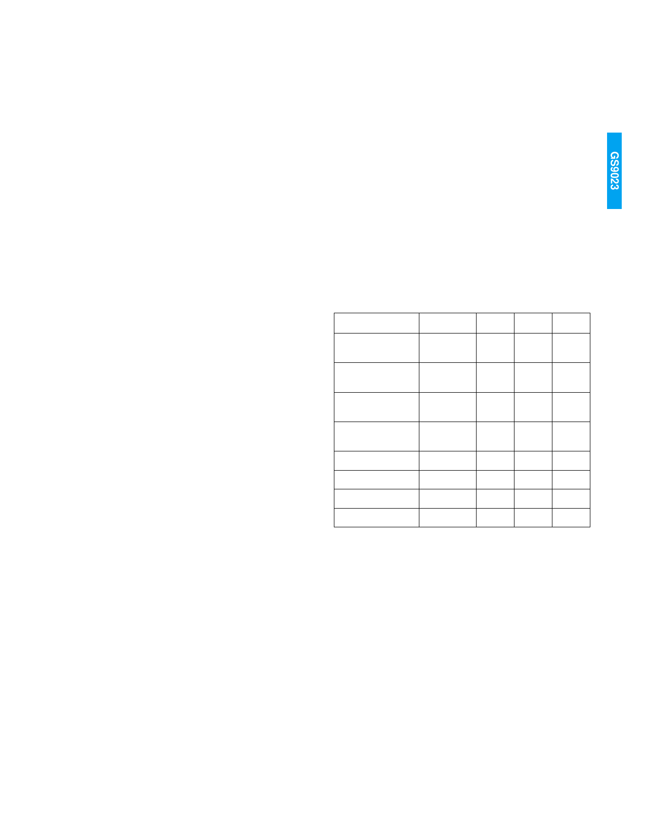
TABLE 2: Audio Input Formats
FORMATS
WCINA/B
AIN-MODE 0
User
Supplied
AIN-MODE 1
User
Supplied
AIN-MODE 2
User
Supplied
AIN-MODE 3
User
Supplied
AIN-AES/EBU
Not Used
Not Used
-
Not Used
-
Not Used
-
AM[2]
0
AM[1]
0
AM[0]
0
0
0
1
0
1
0
0
1
1
1
0
0
1
0
1
1
1
0
1
1
1
Audio Data Input
The serial audio data for channels 1 and 2 are input to the
AINA pin. The serial audio data for channels 3 and 4 are
input to the AINB pin. The GS9023 can multiplex 20 or 24
bit audio data samples. When the AUXEN pin or bit “A4ON”
of Host Interface Register #1h is HIGH, the device
processes 24 bit audio samples. When the AUXEN pin or
“A4ON” register bit is LOW, the device processes 20 bit
audio samples. On power up, the “A4ON” bit default is
LOW.
The GS9023 offers five predefined audio data input formats,
selected via the AM[2:0] pins, which are listed in Table 2
and illustrated in Figure 1. The first four predefined formats
relate to non-AES/EBU audio data while the fifth format
corresponds to the AES/EBU audio format. The WCINA and
WCINB pins should be grounded when inputting AES/EBU
audio data as they are not used.
8
GENNUM CORPORATION
522 - 45 - 05
Share Link: 