MAX11503 查看數據表(PDF) - Maxim Integrated
零件编号
产品描述 (功能)
比赛名单
MAX11503 Datasheet PDF : 8 Pages
| |||
Video Y/C Summer with
Driver and Chroma Mute
DC-Coupled Output
The MAX11503 input clamps the sync tip of the video
signal to 250mV at the IC output, forcing the blanking
level to be about 550mV on the coax cables at the ter-
mination resistor. This allows driving video to meet digi-
tal TV specifications without the need for costly
AC-coupling capacitors. Power dissipation is an espe-
cially important consideration if DC-coupling one or two
terminated video coax cables.
Minimum Supply-Voltage Considerations
The minimum supply voltage depends on the type of
video and the output configuration. Use at least the
minimum supply voltage to preserve the output amplifi-
er’s linearity and video specifications.
The following examples discuss the required minimum
supply voltage under several scenarios. Unless other-
wise specified, these examples assume:
1) The luma input is AC-coupled and therefore the
sync tip is clamped at 0.250V at the output.
2) The output amplifier needs 0.800V of overhead.
PAL
A PAL test signal is 1.235VP-P (100% color bars).
Therefore, the required minimum supply voltage is:
VCC = 2 x 1.235 + 0.250 + 0.800 = 3.5V
NTSC
A NTSC signal is 1.0VP-P (755 color bars). Therefore,
the required minimum supply voltage is:
VCC = 2 x 1.000 + 0.250 + 0.800 = 3.05V
Using SAG Correction
When using SAG correction, the output amplifier needs
an overhead of 800mV, in addition to 130% of the maxi-
mum video level at the output. Assuming an AC-cou-
pled luma input:
For PAL, the minimum required supply voltage is:
VCC = 2 x 1.235 x 1.3 + 0.250 + 0.800 = 4.26V
For NTSC, the minimum required supply voltage is:
VCC = 2 x 1.000 x 1.3 + 0.250 +0.800 = 3.65V
Thermal Considerations
The power dissipation for single 75Ω terminated load is
64mW, and for two 75Ω terminated loads is 106mW. As
a result of the exposed pad, the temperature rise is
minimized.
Short-Circuit Protection
The MAX11503 outputs are fully protected against short
circuits either to the ground or the positive supply of the
device. The short-circuit protection circuitry limits the
output current to 130mA (typical) per output.
PCB Layout Recommendations
The MAX11503 has an exposed pad on the bottom.
The pad should be externally connected to ground.
Place power-supply decoupling capacitors close to the
device with short traces connecting to the power
planes. Use ceramic 0.1µF bypass and 1µF bulk
capacitors.
For a recommended PCB layout, refer to the MAX11503
EV kit data sheet.
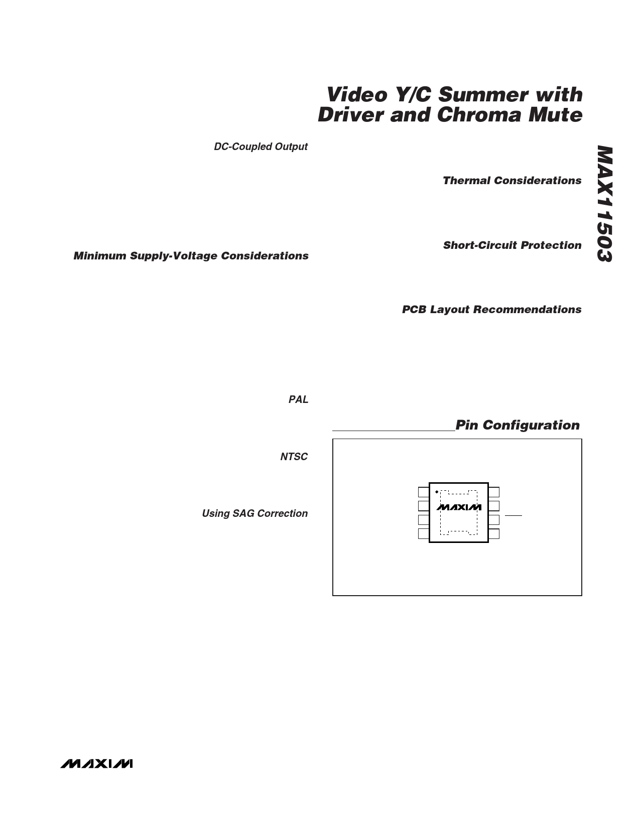
Pin Configuration
TOP VIEW
YIN 1
GND 2
OUT 3
SAG 4
*EXPOSED PAD
MAX11503
*
µMAX
8 CIN
7 CMUTE
6 PSAVE
5 VCC
_______________________________________________________________________________________ 7
Share Link: 