DS2105S 查看數據表(PDF) - Dallas Semiconductor -> Maxim Integrated
零件编号
产品描述 (功能)
比赛名单
DS2105S Datasheet PDF : 7 Pages
| |||
DS2105
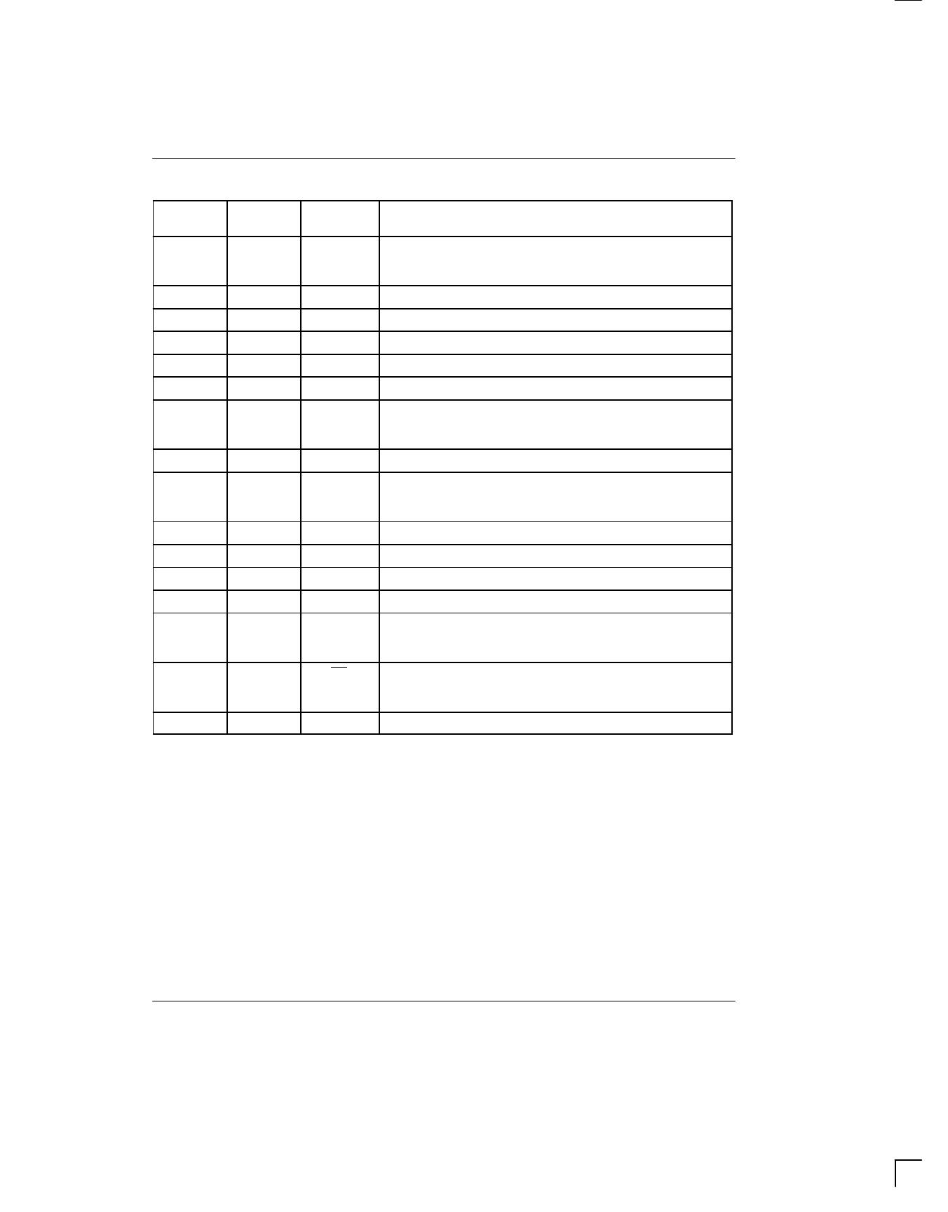
PIN DESCRIPTION Table 1
DS2105S
PIN
DS2105Z
PIN
SYMBOL
DESCRIPTION
1
1
TERMPWR1 Termination Power 1. Should be connected to the SCSI
TERMPWR line. Must be decoupled with either a 2.2 µF or 4.7 µF.
See Figure 2.
2
2
R1
Signal Termination 1. 110 ohm termination.
3
3
R2
Signal Termination 2. 110 ohm termination.
4
4
R3
Signal Termination 3. 110 ohm termination.
5
5
R4
Signal Termination 4. 110 ohm termination.
6
6
R5
Signal Termination 5. 110 ohm termination.
7
7
VREF1 Reference Voltage 1. Must be externally connected directly to
the VREF2 pin. Must be decoupled with a 4.7 µF capacitor as
shown in Figure 2.
8
8
GND
Ground. Signal ground; 0.0V.
9
9
TERMPWR2 Termination Power 2. Should be connected to the SCSI
TERMPWR line. Must be decoupled with either a 2.2 µF or 4.7 µF.
See Figure 2.
10
11
R6
Signal Termination 6. 110 ohm termination.
11
12
R7
Signal Termination 7. 110 ohm termination.
12
13
R8
Signal Termination 8. 110 ohm termination.
13
14
R9
Signal Termination 9. 110 ohm termination.
15
15
VREF2 Reference Voltage 2. Must be externally connected directly to
the VREF1 pin. Must be decoupled with a 4.7 µF capacitor as
shown in Figure 2.
16
16
PD
Power Down. When tied low, the DS2105 enters a power–down
mode. Contains an internal 50K pull–up. Strap low to deactivate
the DS2105, leave open circuited to activate the DS2105.
14
10
NC
No Connect. Do not connect any signal to this pin.
022698 4/7
Share Link: 