IN74HC640ADW 查看數據表(PDF) - Integral Corp.
零件编号
产品描述 (功能)
比赛名单
IN74HC640ADW Datasheet PDF : 5 Pages
| |||
IN74HC640A
AC ELECTRICAL CHARACTERISTICS(CL=50pF,Input tr=tf=6.0 ns)
VCC
Guaranteed Limit
Symbol
Parameter
V 25 °C ≤85°C ≤125 Unit
to
°C
-55°C
tPLH, Maximum Propagation Delay, A to B , B 2.0 75
tPHL to A (Figures 1 and 3)
4.5 15
6.0 13
95 110 ns
19
22
16
19
tPLZ, Maximum Propagation Delay , Direction 2.0 110 140 165 ns
tPHZ or Output Enable to A or B (Figures 2 4.5 22
28
33
and 4)
6.0 19
24
28
tPZL, Maximum Propagation Delay , Direction 2.0 110 140 165 ns
tPZH or Output Enable to A or B (Figures 2 4.5 22
28
33
and 4)
6.0 19
24
28
tTLH, tTHL Maximum Output Transition Time, Any 2.0 60
75
90 ns
Output
4.5 12
15
18
(Figures 1 and 3)
6.0 10
13
15
CIN Maximum Input Capacitance (Pin 1 or -
10
10
10 pF
Pin 19)
COUT Maximum Three-State I/O Capacitance -
15
15
15 pF
(Output in High-Impedance State)
Power Dissipation Capacitance (Per Typical @25°C,VCC=5.0 V
Transceiver Channel)
CPD Used to determine the no-load dynamic
40
pF
power
consumption:
PD=CPDVCC2f+ICCVCC
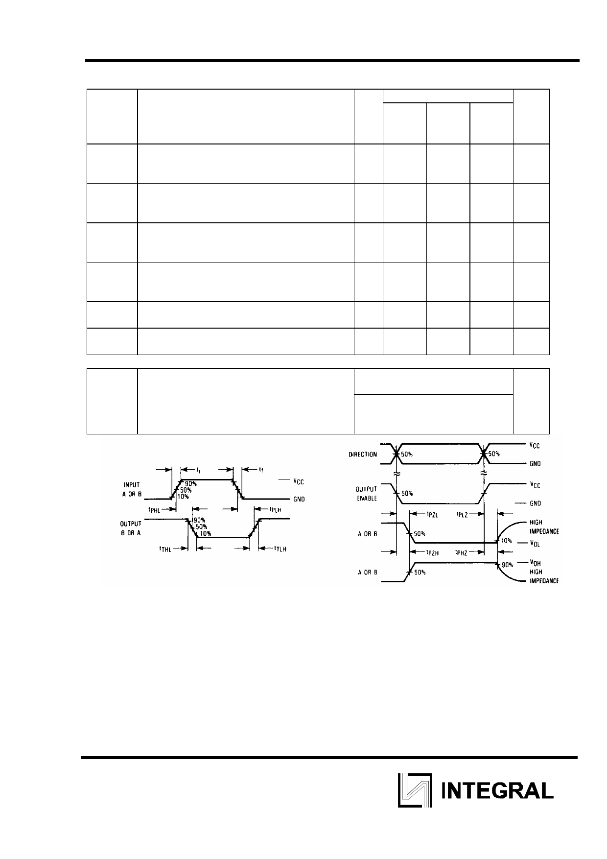
Figure 1. Switching Waveforms
Figure 2. Switching Waveforms
4
Share Link: 