MC74F534 查看數據表(PDF) - Motorola => Freescale
零件编号
产品描述 (功能)
比赛名单
MC74F534 Datasheet PDF : 3 Pages
| |||
MC54 / 74F534
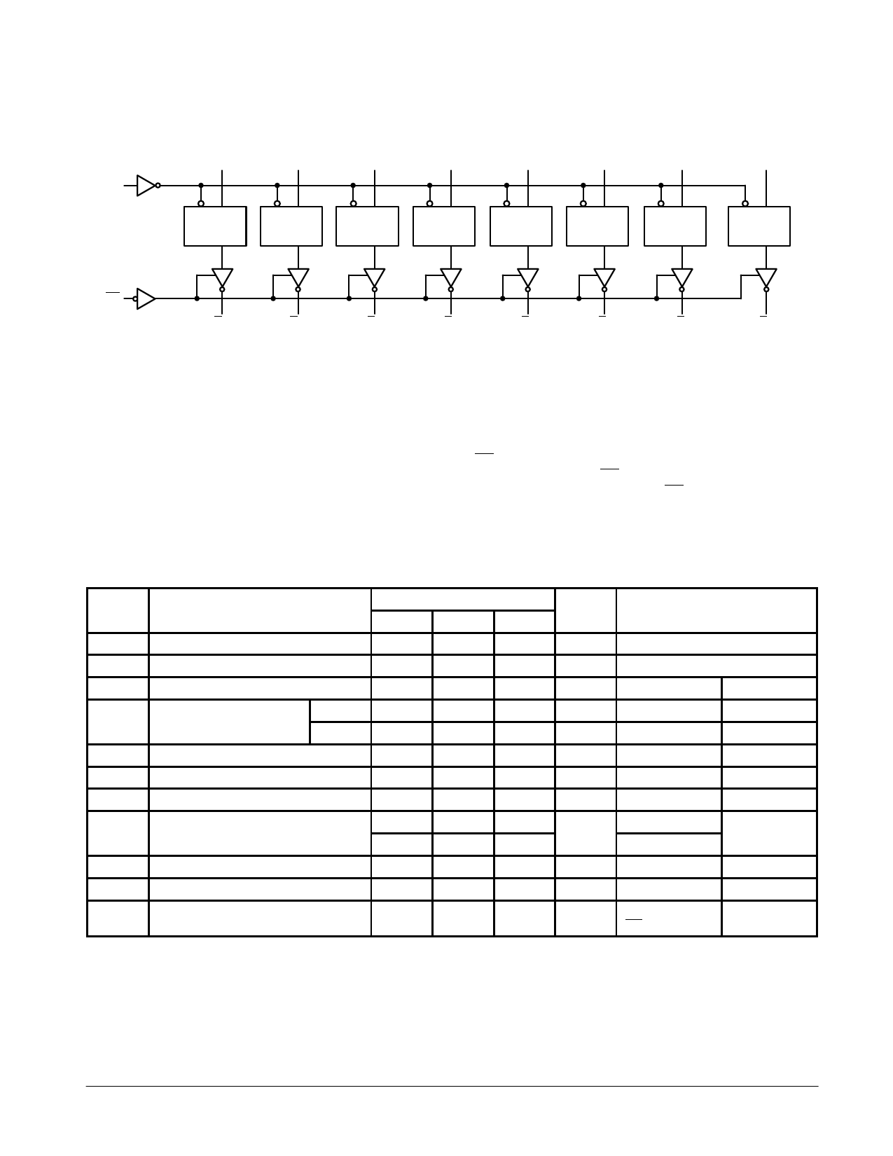
LOGIC DIAGRAM
D0
D1
D2
D3
D4
D5
D6
D7
CP
CP D
Q
CP D
Q
CP D
Q
CP D
Q
CP D
Q
CP D
Q
CP D
Q
CP D
Q
OE
O0
O1
O2
O3
O4
O5
O6
O7
Please note that this diagram is provided only for the understanding of logic operations and should not be used to estimate propagation delays.
FUNCTIONAL DESCRIPTION
The F534 consists of eight edge-triggered flip-flops with
individual D-type inputs and 3-state true outputs. The buffered
clock and buffered Output Enable are common to all flip-flops.
The eight flip-flops will store the state of their individual D
inputs that meet the setup and hold times requirements on the
LOW-to-HIGH Clock (CP) transition. With the Output Enable
(OE) LOW, the contents of the eight flip-flops are available at
the outputs. When the OE is HIGH, the outputs go to the high
impedance state. Operation of the OE input does not affect the
state of the flip-flops.
DC CHARACTERISTICS OVER OPERATING TEMPERATURE RANGE (unless otherwise specified)
Limits
Symbol
Parameter
Min
Typ
Max
Unit
Test Conditions
VIH
Input HIGH Voltage
2.0
VIL
Input LOW Voltage
VIK
Input Clamp Diode Voltage
VOH
Output HIGH Voltage
54, 74
2.4
74
2.7
VOL
IOZH
IOZL
Output LOW Voltage
Output OFF Current — HIGH
Output OFF Current — LOW
IIH
Input HIGH Current
IIL
Input LOW Current
IOS
Output Short Circuit Current (Note 2)
– 60
ICCZ
Power Supply Current
0.8
– 1.2
3.3
3.3
0.35
0.5
50
– 50
20
100
– 0.6
–150
55
86
V
Guaranteed Input HIGH Voltage
V
Guaranteed Input LOW Voltage
V
IIN = – 18 mA
VCC = MIN
V
IOH = – 3.0 mA VCC = 4.5 V
V
IOH = – 3.0 mA VCC = 4.75 V
V
IOL = 24 mA
VCC = MIN
µA
VOUT = 2.7 V
VCC = MAX
µA
VOUT = 0.5 V
VCC = MAX
VIN = 2.7 V
µA
VIN = 7.0 V
VCC = MAX
mA
VIN = 0.5 V
VCC = MAX
mA
VOUT = 0 V
VCC = MAX
mA
Dn = Gnd
OE = 4.5 V
VCC = MAX
NOTES:
1. For conditions such as MIN or MAX, use the appropriate value specified under guaranteed operating ranges.
2. Not more than one output should be shorted at a time, nor for more than 1 second.
FAST AND LS TTL DATA
4-201
Share Link: 