DS2770 查看數據表(PDF) - Maxim Integrated
零件编号
产品描述 (功能)
比赛名单
DS2770 Datasheet PDF : 27 Pages
| |||
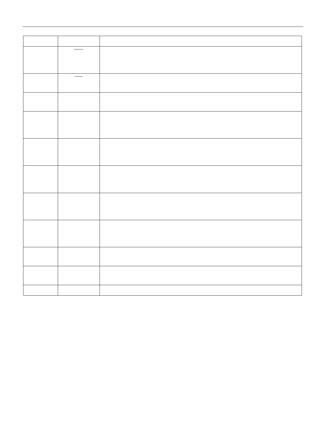
DETAILED PIN DESCRIPTION Table 1
DS2770
PIN
SYMBOL DESCRIPTION
1
UV
Battery Undervoltage Detect Output: This pin allows charge of the
battery at a reduced rate when the battery cell voltage is less than the low
battery voltage threshold, VLB.
2
CC
Charge Control Output: Charge of the battery is controlled through this
pin when battery cell voltage is greater than or equal to VLB.
3
VCH Charge Supply Input: The charge source is connected to this pin and is
measured by the DS2770 to determine if a charge source is present.
4, 5, 6
SNS
Sense Resistor Connection: Connect to the negative terminal of the
battery pack. In the internal sense resistor configuration, the sense resistor
is connected between VSS and SNS.
8
IS2
Current-Sense Input: This pin is internally connected to SNS through a
10kW resistor. Connect a 0.1mF capacitor between IS2 and IS1 to
complete a lowpass filter.
9
IS1
Current-Sense Input: This pin is internally connected to VSS through a
10kW resistor. Connect a 0.1mF capacitor between IS1 and IS2 to
complete a lowpass filter.
11, 12, 13
VSS
Device Ground: Connect directly to the negative terminal of the battery
cell. For the external sense resistor configuration, connect the sense
resistor between VSS and SNS.
14
DQ
Data Input/Out: 1-Wire data line. Open-drain output driver. Connect this
pin to the DATA terminal of the battery pack. Pin has an internal pull-
down for sensing disconnection.
15
VIN
Voltage Sense Input: The voltage on the battery cell is monitored via this
input pin.
16
VDD Power Supply Input: Input supply voltage for the DS2770 (2.7V to
5.5V)
7, 10
NC
Do not connect.
4 of 27
Share Link: 