ISL8510 查看數據表(PDF) - Renesas Electronics
零件编号
产品描述 (功能)
比赛名单
ISL8510 Datasheet PDF : 21 Pages
| |||
ISL8510
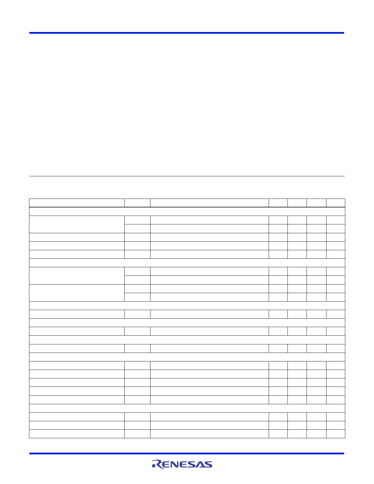
Absolute Maximum Ratings (Note 1)
VIN to GND . . . . . . . . . . . . . . . . . . . . . . . . . . . . GND -0.3V to +26V
VIN_LDO to GND. . . . . . . . . . . . . . . . . . . . . . . . . GND -0.3V to +6V
BOOT to GND . . . . . . . . . . . . . . . . . . . . . . . . . . GND -0.3V to +33V
PHASE to BOOT . . . . . . . . . . . . . . . . . . . . . . . . . . . . . . -6V to +0.3V
VCC to GND . . . . . . . . . . . . . . . . . . . . . . . . . . . . GND -0.3V to +6V
VOUT, LDO . . . . . . . . . . . . . . . . . . . . . . . . . . . . . GND -0.3V to +6V
FB_PWM, FB_LDO to GND. . . . . . . . . . . . . . . . . GND -0.3V to +6V
PG_PWM, PG_LDO to GND . . . . . . . . . . . . . . . . GND -0.3V to +6V
EN, EN_LDO to GND. . . . . . . . . . . . . . . . . . . . . . GND -0.3V to +6V
CC to GND. . . . . . . . . . . . . . . . . . . . . . . . . . . . . . GND -0.3V to +6V
VCC Output Current. . . . . . . . . . . . . . . . . . . . . . . . . . . . . . . . . 50mA
Thermal Information
Thermal Resistance
JA (°C/W) JC (°C/W)
QFN Package (Notes 2, 3). . . . . . . . . .
36
5
Maximum Junction Temperature (Plastic Package) . . . . . . . +150°C
Maximum Storage Temperature Range . . . . . . . . . .-65°C to +150°C
Ambient Temperature Range. . . . . . . . . . . . . . . . . . .-40°C to +85°C
Junction Temperature Range. . . . . . . . . . . . . . . . . .-40°C to +125°C
Pb-free Reflow Profile . . . . . . . . . . . . . . . . . . . . . . . See Link Below
http://www.intersil.com/pbfree/Pb-FreeReflow.asp
CAUTION: Do not operate at or near the maximum ratings listed for extended periods of time. Exposure to such conditions may adversely impact product reliability and
result in failures not covered by warranty.
NOTES:
1. An accidental short between VCC and GND may cause excessive heating and permanent damage to the device.
2. JA is measured in free air with the component mounted on a high effective thermal conductivity test board with “direct attach” features. See
Tech Brief TB379 for details.
3. For JC, the “case temp” location is the center of the exposed metal pad on the package underside.
Electrical Specifications
Unless Otherwise Noted, Typical Specifications are Measured at the Following Conditions: TA = +25°C,
VIN = 6V to 25V. Parameters with MIN and/or MAX limits are 100% tested at +25°C, unless otherwise specified.
Temperature limits established by characterization and are not production tested.
PARAMETER
SYMBOL
TEST CONDITIONS
MIN TYP MAX UNITS
SUPPLY VOLTAGE
VIN Voltage Range
VIN
5.5
25
V
VIN connected to VCC
4.5
5.0
5.5
V
VIN_LDO Voltage Range
(Note 7)
1.8
4.6
V
VIN Operating Supply Current
VIN Shutdown Supply Current
POWER-ON RESET
IOP (Note 4)
ISD EN_PWM = EN_LDO = GND
2.5
3.5
mA
70
100
A
VCC POR Threshold
Rising Edge
4.25 4.40 4.50
V
Hysteresis
260
mV
VIN_LDO POR Threshold
Rising Edge
1.2
V
Hysteresis
200
mV
INTERNAL VCC LDO
VCC Output Voltage Range
REFERENCE
VIN = 6V to 25V, IVCC = 0mA to 50mA
4.5 5.00 5.5
V
Reference Voltage
STANDARD BUCK PWM REGULATOR
VFB VIN = 6V to 25V, IREF = 0
0.590 0.6 0.609 V
FB_PWM Line Regulation
OSCILLATOR and PWM MODULATOR
IOUT = 0mA, VIN = 6V to 25V
-0.5
0.5
%
Nominal Switching Frequency
Modulator Gain
Peak-to-Peak Sawtooth Amplitude
PWM Ramp Offset Voltage
Maximum Duty Cycle
ERROR AMPLIFIER
fSW
AMOD
VRAMP
VOFFSET
DCMAX
TA = -40°C to +85°C, VCC = 5V
VIN = 12V (AMOD = 10/VIN)
VIN = 12V (VP-P = VIN/10)
COMP >4V
450 500 550 kHz
0.73 0.86 0.99 V/V
1.2
V
0.70 0.8 0.91
V
80
83
%
Open-Loop Gain
88
dB
Gain Bandwidth Product
GBWP
15
MHz
Slew Rate
SR COMP = 10pF
5
V/µs
FN6516 Rev 2.00
December 15, 2008
Page 6 of 21
Share Link: 