M56789 查看數據表(PDF) - MITSUBISHI ELECTRIC
零件编号
产品描述 (功能)
比赛名单
M56789 Datasheet PDF : 15 Pages
| |||
MITSUBISHI <CONTROL / DRIVER IC>
M56789FP
4 CHANNEL ACTUATOR DRIVER
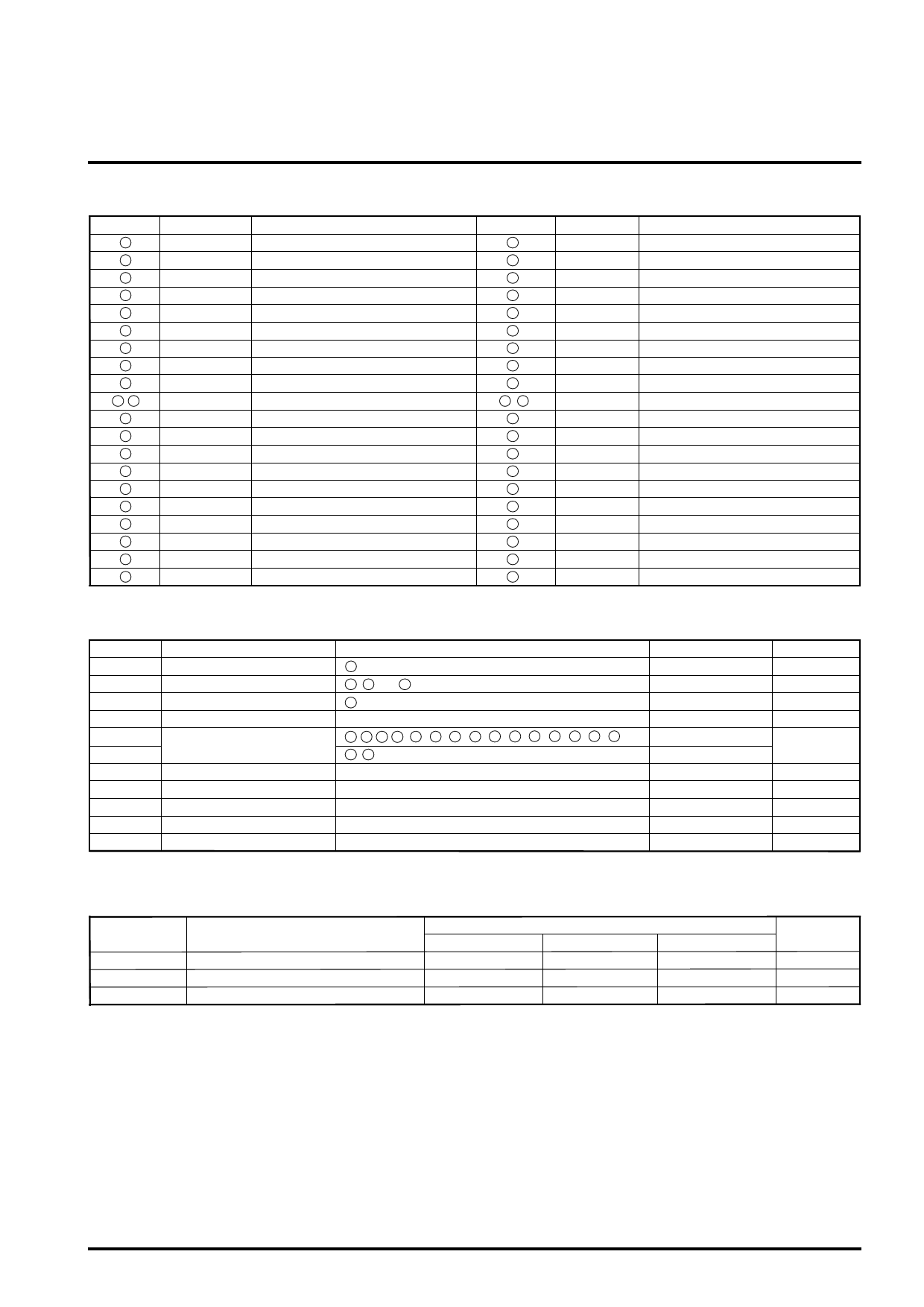
PIN DESCRIPTIONS
Pin No.
1
2
3
4
5
6
8
9
10
7 , 11
12
13
14
15
16
17
18
19
20
21
Symbol
MUTE2
MUTE1
SOUT2
SIN2-
IN2+
IN2-
OUT2
VM2(-)
VM2(+)
GND
VM1(+)
VM1(-)
OUT1
IN1-
IN1+
Vm1
SIN1-
SOUT1
VCC1
OP2OUT
Function
CH4 mute
CH1,2 and 3 mute
S2 amplifier output
S2 amplifier inverted input
E2 amplifier non-inverted input
E2 amplifier inverted input
E2 amplifier output
CH2 inverted output
CH2 non-inverted output
GND
CH1 non-inverted output
CH1 inverted output
E1 amplifier output
E1 amplifier inverted input
E1 amplifier non-inverted input
Motor power supply - 1
S1 amplifier inverted input
S1 amplifier output
5V power supply
OP2 amplifier output
Pin No.
42
41
40
39
38
37
36
35
34
29 , 33
32
31
30
28
27
26
25
24
23
22
Symbol
VCC2
VREF
VREFO
IN3-
IN3+
Vm3
OUT3
VM3(-)
VM3(+)
GND
VM4(+)
VM4(-)
IN4A-
Vm2
IN4B-
OP1OUT
OP1-
OP1+
OP2+
OP2-
Function
Bootstrap power supply
Reference voltage input
Reference voltage output
E3 amplifier inverted input
E3 amplifier non-inverted input
Motor power supply - 3
E3 amplifier output
CH3 inverted output
CH3 non-inverted output
GND
CH4 non-inverted output
CH4 inverted output
E4 amplifier low gain input
Motor power supply - 2
E4 amplifier high gain input
OP1 amplifier output
OP1 amplifier inverted input
OP1 amplifier non-inverted input
OP2 amplifier non-inverted input
OP2 amplifier inverted input
ABSOLUTE MAXIMUM RATING (Ta=25˚C )
Symbol
VCC2
Vm
VCC1
Io
Vin1
Vin2
Pt
Kθ
Tj
Topr
Tstg
Parameter
Bootstrap power supply
Motor power supply
5V power supply
Output Current
Maximum input voltage
of terminals
Power dissipation
Thermal derating
Junction temperature
Operating temperature
Storage temperature
Conditions
42 pin input voltage
17 , 28 and 37 pins input voltage
20 pin input voltage
1 , 2 , 5 , 6 , 15 , 16 , 22 , 23 , 24 , 25 , 27 , 30 , 38 , 39 , 41 pins
4 , 18 pins
Free Air
Free Air
Rating
15
15
7.0
700
0 – VCC1
0 – Vm1
1.2
9.6
150
-20 – +75
-40 – +150
Unit
V
V
V
mA
V
W
mW / ˚C
˚C
˚C
˚C
RECOMMENDED OPERATING CONDITIONS
Symbol
Parameter
Min.
VCC1
5V power supply
4.5
VCC2
Bootstrap power supply
Vm1, 2, 3
Motor power supply-1, 2, 3
Limits
Typ.
5.0
Vm + 1.0
5.0
Unit
Max.
5.5
V
V
V
Share Link: 