M54HCT540F1R 查看數據表(PDF) - STMicroelectronics
零件编号
产品描述 (功能)
比赛名单
M54HCT540F1R
STMicroelectronics

M54HCT540F1R Datasheet PDF : 12 Pages
| |||
M54/M74HCT540/541
AC ELECTRICAL CHARACTERISTICS (CL = 50 pF, Input tr = tf = 6 ns)
Symbol
Parameter
Test Conditions
VCC CL
(V) (pF)
tTLH Output Transition 4.5 50
tTHL Time
tPLH Propagation
tPHL Delay Time
(for HCT540)
4.5 50
4.5 150
TA = 25 oC
54HC and 74HC
Value
-40 to 85 oC -55 to 125 oC Unit
74HC
54HC
Min. Typ. Max. Min. Max. Min. Max.
6
12
15
18
ns
12 20
25
30
ns
16 25
31
38
ns
tPLH Propagation
tPHL Delay Time
(for HCT541)
4.5 50
4.5 150
14 23
29
35
ns
18 28
35
42
ns
tPZL Output Enable
4.5 50 RL = 1KΩ
18 30
38
45
ns
tPZH Time
4.5 150 RL = 1KΩ
22 34
43
51
ns
tPLZ Output Disable
4.5 50 RL = 1KΩ
19 27
34
41
ns
tPHZ Time
CIN Input Capacitance
5
10
10
10 pF
CPD (*) Power Dissipation
34
Capacitance
pF
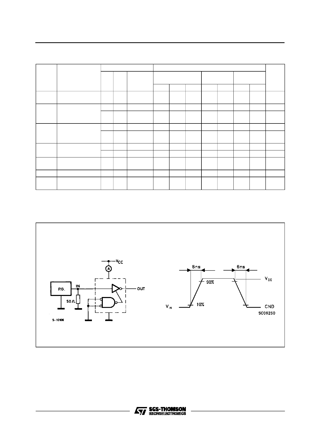
(*) CPD is defined as the value of the IC’s internal equivalent capacitance which is calculated from the operating current consumption without load.
(Refer to Test Circuit). Average operting current can be obtained by the following equation. ICC(opr) = CPD •VCC •fIN + ICC/8 (per gate)
TEST CIRCUIT ICC (Opr.)
HCT 54 0
6/12
Share Link: