HS-82C85RH(2000) 查看數據表(PDF) - Intersil
零件编号
产品描述 (功能)
比赛名单
HS-82C85RH Datasheet PDF : 16 Pages
| |||
HS-82C85RH
Functional Description
The HS-82C85RH Static Clock Controller/Generator
provides simple and complete control of static CMOS
system operating modes. The HS-82C85RH can operate
with either an external crystal or an external frequency
source and can support full speed, slow, stop-clock and
stop-oscillator operation. While it is directly compatible with
the Intersil HS-80C86RH CMOS 16-bit static
microprocessor, the HS-82C85RH can also be used for
general purpose system clock control.
Separate signals are provided on the HS-82C85RH for stop
and start control of the crystal oscillator and clock outputs. A
single control line determines fast (crystal/EFI frequency
divided by 3) or slow (crystal/EFI frequency divided by 768)
mode operation. A clock synchronization input is provided to
allow the use of multiple HS-82C85RHs in the same system.
The HS-82C85RH generates the proper HS-80C86RH reset
pulse, and it also handles all data transfer timing by
generating the HS-80C86RH ready signal.
Automatic maximum mode HS-80C86RH software HALT
instruction decode logic is present to ease the design of
software-based clock control systems and provides
complete software control of STOP mode operation.
Automatic minimum mode software HALT instruction
decoding can be easily implemented with a single 74HC74
device. Restart logic insures valid clock start-up and
complete synchronization of CLK, CLK50 and PCLK.
Static Operating Modes
The HS-82C85RH Static Clock Controller can be dynamically
set to operate in any one of four modes at any one time: FAST,
SLOW, STOP-CLOCK and STOP-OSCILLATOR. Each mode
has distinct power and performance characteristics which
can be matched to the needs of a particular system at a
specific time (see Table 1).
Keep in mind that a single system may require all of these
operating modes at one time or another during normal
operation. A design need not be limited to a single operating
mode or a specific combination of modes. The appropriate
operating mode can be matched to the power-performance
level needed at a specific time or in a particular
circumstance.
Reset Logic
The HS-82C85RH reset logic provides a Schmitt trigger
input (RES) and a synchronizing flip-flop to generate there
set timing. The reset signal is synchronized to the falling
edge of CLK. A simple RC network can be used to provide
power-on reset by utilizing this function of the HS-82C85RH.
When in the crystal oscillator (F/C = LOW) or the EFI (F/C =
HIGH) mode, a LOW state on the RES input will set the
RESET output to the HIGH state. It will also restart the
oscillator circuit if it is in the idle state. The RESET output is
guaranteed to stay in the HIGH state for a minimum of 16
CLK cycles after a low-to-high transition of the RES input.
An oscillator restart count sequence will not be disturbed
by RESET if this count is already in progress. After the
restart counter expires, the RESET output will stay HIGH at
least for 16 periods of CLK before going LOW. RESET can
be kept high beyond this time by a continuing low input on
the RES input.
If F/C is low (crystal oscillator mode), a low state on RES
starts the crystal oscillator circuit. The stopped outputs
remain inactive, until the oscillator signal amplitude reaches
the X1 Schmitt trigger input threshold voltage and 8192
cycles of the crystal oscillator output are counted by an
internal counter. After this count is complete, the stopped
outputs (CLK, CLK50, PCLK) start cleanly with the proper
phase relationships.
This 8192 count requirement insures that the CLK, CLK50
and PCLK outputs will meet minimum clock requirements
and will not be affected by unstable oscillator characteristics
which may exist during the oscillator start-up sequence. This
sequence is also followed when a START command is
issued while the HS-82C85RH oscillator is stopped.
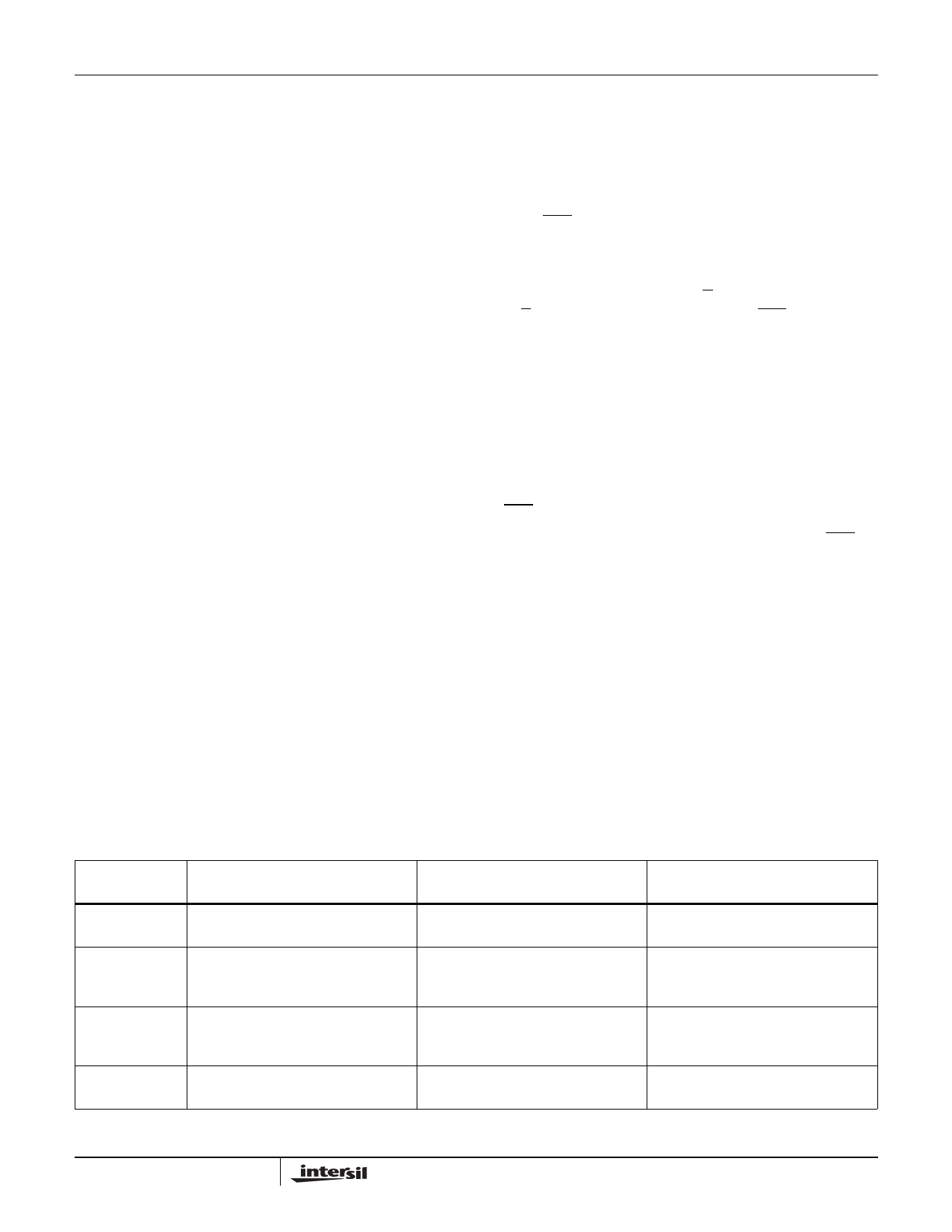
TABLE 1. STATIC SYSTEM OPERATING MODE CHARACTERISTICS
OPERATING
MODE
DESCRIPTION
POWER LEVEL
PERFORMANCE
Stop-Oscillator
All system clocks and main clock
oscillator are stopped
Maximum savings
Slowest response due to oscillator
restart time
Stop-Clock
System CPU and peripherals clocks Reduced system power
stop but main clock oscillator continues
to run at rated frequency
Fast restart - no oscillator restart time
Slow
System CPU clocks are slowed while
peripheral clock and main clock
oscillator run at rated frequency
Power dissipation slightly higher than
Stop-Clock
Continuous operation at low frequency
Fast
All clocks and oscillators run at rated Highest power
frequency
Fastest response
11
Share Link: 