M52347FP 查看數據表(PDF) - MITSUBISHI ELECTRIC
零件编号
产品描述 (功能)
比赛名单
M52347FP Datasheet PDF : 13 Pages
| |||
APPLICATION METHOD
1. Input block
1) GREEN (SYNC ON VIDEO) IN (Pin 3 )
Input with sync negative polarity.
Comparison of pin 4 input signal and the reference voltage of
the inside of the IC performs the synchronous separation. When
the input at pin 4 is less than or equal to the reference voltage
(2.8V) and the flowing current is more than or equal to the input
sensitivity current (200 µ A or more), the signal is separated.
When only a synchronous signal is input into pin 4 , the
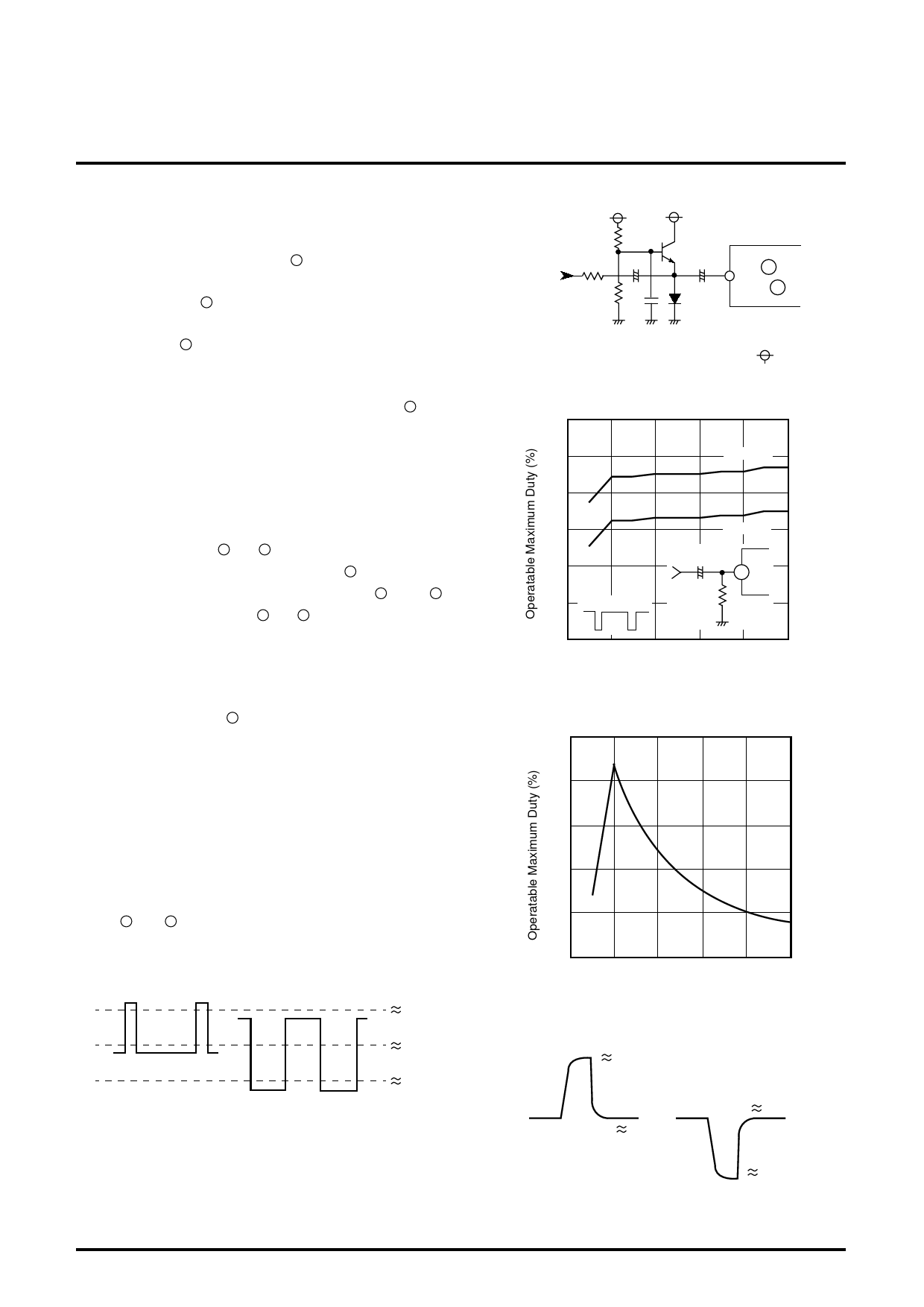
operatable amplitude and the duty are as shown in Figure 1.
If the IC does not operate normally with the video signal input,
change the value of external resistance R to make the current
optimum.
But, when capacity value is too big, output response
becomes bad.
2) COMP/H IN, VIN (pins 6 and 8 )
The composite sync input is connected to pin 6 . H and V of the
separate sync input are connected to pins 6 and 8 ,
respectively. For each of pins 6 and 8 , the bias is 2.5V and the
impedance is 10 kΩ. The internal double threshold converter is
used for shaping waveform and for detecting polarity.
Average DC voltage of input signal is 2.5V. Each threshold
voltage is set at a voltage ±0.3V away from this voltage.
If the duty ratio at pin 6 is small as shown in Figure 2, the
optimum value is approx. 0.3 VP-P. If the duty ratio is large, the
optimum value is approx. 0.6 VP-P. Figure 3 shows the allowable
input amplitude and the reference value of duty test.
Only 5V TTL input, decrease the amplitude by resistor
splitting.
In addition, Figure 4 shows an example for improving the
capability of the allowable duty when the input amplitude is 0.7
VP-P or more.
To use the IC out of the standard value, remove the filter from
pins 7 and 9 , observe the waveform and check for a match
with the waveform shown in Figure 5.
Small POSI Duty
Lsrge NEG Duty
Fig. 2
2.8V
2.5V
2.2V
MITSUBISHI ICs (Monitor)
M52347SP/FP
SYNC SIGNAL PROCESSOR
18kΩ
Input signal
100Ω
3kΩ
pin 6
or pin 8
This additional circuit (limiter) limits
the amplitude to 0.6 VP-P.
: 5V
Fig. 4
30
25
R=56kΩ
20
15
10
5
f=100kHz
R=75kΩ
3.3µ
4
R
0
0
0.2
0.4
0.6
0.8
1.0
Input Amplitude (VP-P)
Fig. 1
50
40
30
20
10
0
0
0.5
1
1.5
2
2.5
Input Amplitude (VP-P)
Fig. 3
4.5V
POSI input
2.5V
Fig. 5
NEG input
2.5V
0.5V
10
Share Link: 