UTCMC34018 查看數據表(PDF) - Unisonic Technologies
零件编号
产品描述 (功能)
比赛名单
UTCMC34018 Datasheet PDF : 14 Pages
| |||
UTCMC34018 LINEAR INTEGRATED CIRCUIT
which receives 3 inputs: a) the Rx-Tx comparator, b) the transmit detector comparator, and c)the volume control.
The response of the attenuators is based on the difference of the ACF voltage from VCC, and therefore a simple
method for monitoring the circuit operation is to monitor this voltage difference(referred to as ∆Vacf).If ∆Vacf is
approximately 150 millivolts the circuit is in the receive mode. If ∆Vacf is approximately 75 millivolts the circuit is in
the idle mode, and two attenuators are at gain setting approximately half way(in dB) between their fully on and fully
off positions.
The maximum gain and attenuation values are determined by the three resistors RR,RTX,RRX(referred to
Fig2,3,4).RR affects both attenuators according to its value RELATIVE to RTX and RRX, which is why Fig 4
indicates the variations versus the ratio of the other resistors to RR.(GRX and GTX are the maximum gains, and
ARX and ATX are maximum attenuations).RTX affects the gain and attentuator according to Fig 3.As can be seen
from the figures, the gain difference(from on to off) is a reasonably constant 45dB until the upper gain limit is
approached. A value of 30K is recommended for RR as a starting point, and then RTX and RRX selected to suit the
particular design goals.
The input impedance of the attenuators (at TXI and RXI) is typically 5.0k ohms, and the maximum input signal
which will not cause output distortion is 250mVrms(707mVp-p).The 4300 ohms resistor and 0.01µCapacitor at
RXO(in fig 1)filters out high frequency components in the receive path. This helps minimize high frequency acoustic
feedback problems which may occur if the filter were not present. The filter's insertion loss is a 1.5dB at
1.0kHz.The outputs of the attenuators are inverted from their inputs.
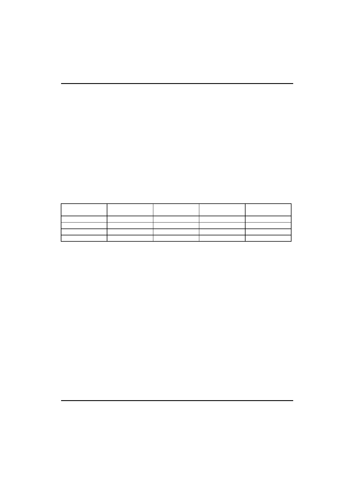
Referring to the attenuator control block, the ∆Vacf voltage at its output is determined by three inputs. The
relationship of the inputs and outputs is summarized in the following truth table.
TX-RX COMP
TRANSMIT DET
COMP
VOLUME
CONTROL
∆VACF
MODE
Transmit
Transmit
No Effect
6.0mV
Transmit
Transmit
Idle
No Effect
75mV
Idle
Receive
Transmit
Affects ∆Vacf
50-150mV
Receive
Receive
Idle
Affects ∆Vacf
50-50mV
Receive
As can be seen from the truth table, the Tx-Rx comparator dominates. The transmit detector comparator is
effective only in the receive mode.
The Tx-Rx comparator is in the transmit position when there is sufficient transmit signal present over and
above any receive signal. The transmit detector comparator then determined whether the transmit signal is a result
of background noise(1 relatively stable signal),or speech which consists of bursts.If the signal is due to background
noise, the attenuators will be put into the idle mode(∆Vacf=75mV).If the signal consists of speech, the attenuator will
be switched to the transmit mode(∆Vacf=6.0mV).A further explanation of this function will be found in the section on
the transmit detector circuit.
The Rx-Tx Comparator is in the receive position when there is sufficient receive signal to overcome the
background noise AND any speech signals. The ∆Vacf voltage will now be 150mV IF the volume control is at the
maximum position, i.e. VLC(pin 24)=VB. If VLC is less than Vb, the gain of the receive attenuator, will vary in a
complementary manner as shown in fig 5.It can be seen that at the minimum recommended operating
level(VLC=0.55VB) the gain of the transmit atternuator is actually greater than that of the receive attenuator. The
effect of varying VLC is to vary ∆Vacf, with a resulting variation in the gains of the attenuators, Fig 6 shows the
gain variation with ∆Vacf.
The capacitor at ACF(pin 25) smoothes the transition between operating modes. This keeps down any "clicks"
in the speaker or transmit signal when the ACF voltage switches.
The gain separation of the two attenuators can be reduced from the typical 45dB by adding a resistor between
pin 20(VCC) and pin 25(ACF).The effect is a reduction of the maximum ∆Vacf voltage in receive mode, while not
affecting ∆Vacf in the transmit mode. as an example, adding a 12 k ohms resistor will reduce ∆Vacf by approximately
15mV(to 135mV).decrease the gain of the receive attenuator by approximately 5.0dB, and increase the gain of the
transmit attenuator by a similar amount. If the circuit requires the receive attenuator gain to be +6.0dB in the receive
mode, RRX must be adjusted (to 27k ohms) to re-establish this value. This change will also increase the receive
attenuator gain in the transmit mode by a similar amount. The resistor at TLI may also require
changing to reset the sensitivity of the thansmit level detector.
UTC
UNISONIC TECHNOLOGIES CO., LTD. 6
QW-R108-006,A
Share Link: 