IRF120 查看數據表(PDF) - Intersil
零件编号
产品描述 (功能)
比赛名单
IRF120 Datasheet PDF : 7 Pages
| |||
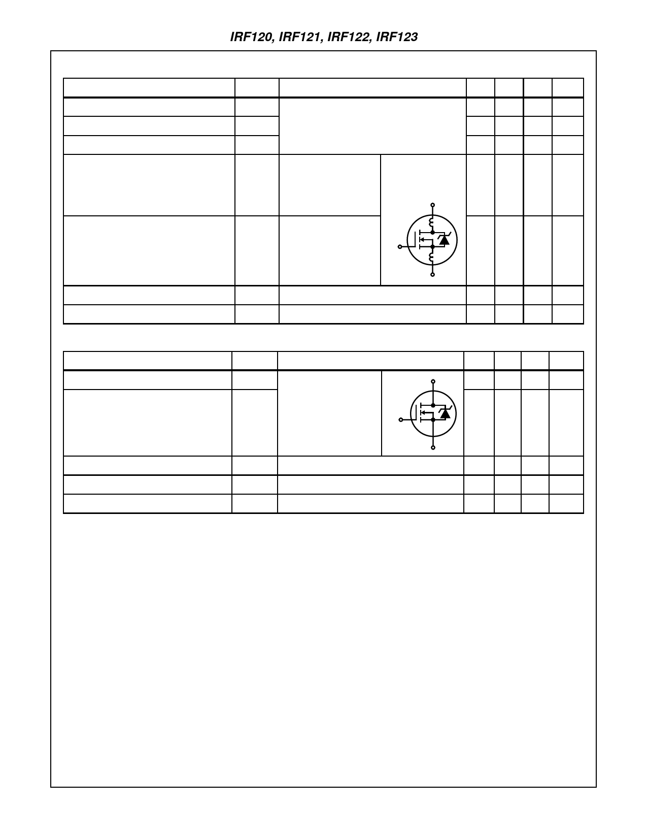
IRF120, IRF121, IRF122, IRF123
Electrical Specifications TC = 25oC, Unless Otherwise Specified (Continued)
PARAMETER
SYMBOL
TEST CONDITIONS
MIN TYP MAX UNITS
Input Capacitance
Output Capacitance
Reverse Transfer Capacitance
Internal Drain Inductance
CISS
COSS
VDS = 25V, VGS = 0V, f = 1MHz
(Figure 11)
- 350 -
pF
- 130 -
pF
CRSS
-
36
-
pF
LD Measured Between the Modified MOSFET
- 5.0 -
nH
Contact Screw on the Symbol Showing the
Flange that is Closer to Internal Device
Source and Gate Pins and Inductances
the Center of Die
D
Internal Source Inductance
LS Measured From the
Source Lead, 6mm
(0.25in) From the Flange G
and the Source Bonding
Pad
LD
- 12.5 -
nH
LS
S
Thermal Resistance, Junction to Case
Thermal Resistance, Junction to Ambient
RθJC
RθJA
Free Air Operation
-
-
2.5 oC/W
-
-
30 oC/W
Source to Drain Diode Specifications
PARAMETER
SYMBOL
TEST CONDITIONS
Continuous Source to Drain Current
Pulse Source to Drain Current
(Note 3)
ISD
ISDM
Modified MOSFET
Symbol Showing the
Integral Reverse P-N
Junction Rectifier
D
G
MIN TYP MAX UNITS
-
- 8.0
A
-
- 32
A
S
Source to Drain Diode Voltage (Note 2)
Reverse Recovery Time
Reverse Recovery Charge
VSD
trr
QRR
TJ = 25oC, ISD = 9.2A, VGS = 0V (Figure 13)
TJ = 25oC, ISD = 9.2A, dISD/dt = 100A/µs
TJ = 25oC, ISD = 9.2A, dISD/dt = 100A/µs
-
- 2.5
V
55 110 240 ns
0.25 0.53 1.10 µC
NOTES:
2. Pulse test: pulse width ≤ 300µs, duty cycle ≤ 2%.
3. Repetitive rating: pulse width limited by maximum junction temperature. See Transient Thermal Impedance curve (Figure 3).
4. VDD = 25V, starting TJ = 25oC, L = 640µH, RG = 25Ω, peak IAS= 9.2A (Figures 15, 16).
2-3
Share Link: 