4501 查看數據表(PDF) - MITSUBISHI ELECTRIC
零件编号
产品描述 (功能)
比赛名单
4501 Datasheet PDF : 113 Pages
| |||
MITSUBISHI MICROCOMPUTERS
4501 Group
SINGLE-CHIP 4-BIT CMOS MICROCOMPUTER
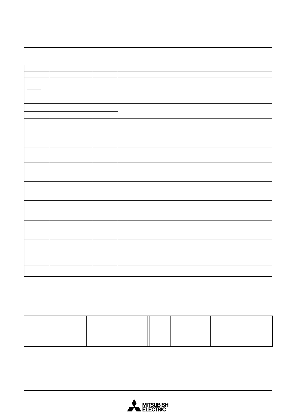
PIN DESCRIPTION
Pin
Name
VDD
Power supply
VSS
Ground
CNVSS
CNVSS
RESET
Reset input/output
XIN
XOUT
D0–D3
System clock input
System clock output
I/O port D
P00–P03
I/O
P10–P13 I/O port P1
P20, P21 I/O port P2
Port C
I/O port C
Port K
I/O port K
CNTR
Timer input/output
INT
AIN0–AIN1
Interrupt input
Analog input
Input/Output
Function
—
Connected to a plus power supply.
—
Connected to a 0 V power supply.
—
Connect CNVSS to VSS and apply “L” (0V) to CNVSS certainly.
I/O
An N-channel open-drain I/O pin for a system reset. When the watchdog timer or the
voltage drop detection circuit cause the system to be reset, the RESET pin outputs
“L” level.
Input
Output
I/O pins of the system clock generating circuit. When using a ceramic resonator, connect
it between pins XIN and XOUT. A feedback resistor is built-in between them. When using
the RC oscillation, connect a resistor and a capacitor to XIN, and leave XOUT pin open.
I/O
Each pin of port D has an independent 1-bit wide I/O function. Each pin has an out-
put latch. For input use, set the latch of the specified bit to “1.” Input is examined by
skip decision. The output structure is N-channel open-drain. Ports D2 and D3 are
equipped with a pull-up function and a key-on wakeup function. Both functions can
be switched by software.
Ports D2 and D3 are also used as ports C and K, respectively.
I/O
Port P0 serves as a 4-bit I/O port, and it can be used as inputs when the output latch
is set to “1.” The output structure is N-channel open-drain. Port P0 has a key-on
wakeup function and a pull-up function. Both functions can be switched by software.
I/O
Port P1 serves as a 4-bit I/O port, and it can be used as inputs when the output latch
is set to “1.” The output structure is N-channel open-drain. Port P1 has a key-on
wakeup function and a pull-up function. Both functions can be switched by software.
Ports P12 and P13 are also used as CNTR and INT, respectively.
I/O
Port P2 serves as a 2-bit I/O port, and it can be used as inputs when the output latch
is set to “1.” The output structure is N-channel open-drain. Port P2 has a key-on
wakeup function and a pull-up function. Both functions can be switched by software.
Ports P20 and P21 are also used as AIN0 and AIN1, respectively.
I/O
1-bit I/O port. Port C can be used as inputs when the output latch is set to “1.” The
output structure is N-channel open-drain. Port C has a key-on wakeup function and
a pull-up function. Both functions can be switched by software. Port C is also used
as port D2.
I/O
1-bit I/O port. Port K can be used as inputs when the output latch is set to “1.” The
output structure is N-channel open-drain. Port K has a key-on wakeup function and
a pull-up function. Both functions can be switched by software. Port K is also used
as port D3.
I/O
CNTR pin has the function to input the clock for the timer 2 event counter, and to out-
put the timer 1 or timer 2 underflow signal divided by 2. This pin is also used as port
P12.
Input
INT pin accepts external interrupts. It has the key-on wakeup function which can be
switched by software. This pin is also used as port P13.
Input
A-D converter analog input pins. AIN0 and AIN1 are also used as ports P20 and P21,
respectively.
MULTIFUNCTION
Pin
D2
D3
P12
P13
Multifunction
C
K
CNTR
INT
Pin
C
K
CNTR
INT
Multifunction
D2
D3
P12
P13
Pin
P20
P21
Multifunction
AIN0
AIN1
Notes 1: Pins except above have just single function.
2: The input/output of D2, D3, P12 and P13 can be used even when C, K, INT and CNTR (input) are selected.
3: The input of P12 can be used even when CNTR (output) is selected.
4: The input/output of P20, P21 can be used even when AIN0, AIN1 are selected.
Pin
AIN0
AIN1
Multifunction
P20
P21
4
Share Link: 