MAX710 查看數據表(PDF) - Maxim Integrated
零件编号
产品描述 (功能)
比赛名单
MAX710 Datasheet PDF : 12 Pages
| |||
MAX710/MAX711
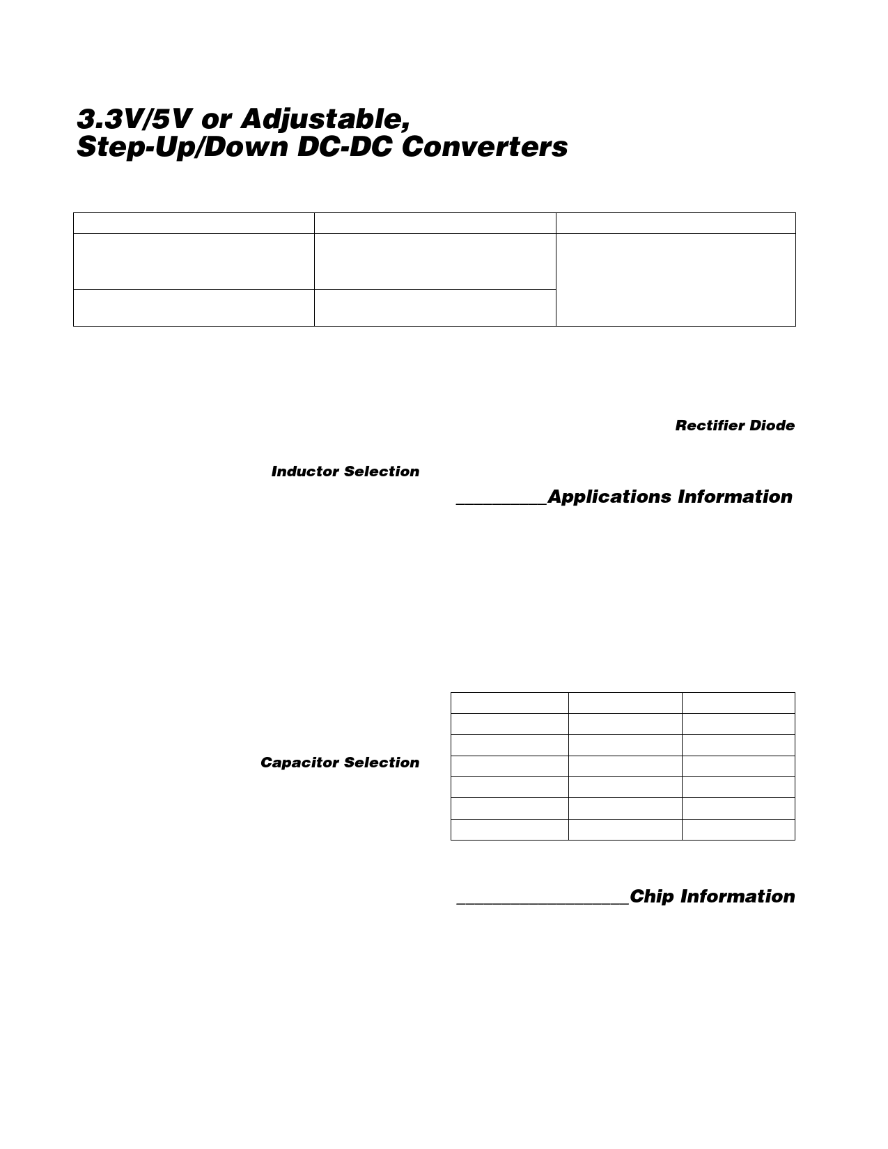
3.3V/5V or Adjustable,
Step-Up/Down DC-DC Converters
Table 2. Component Selection
INDUCTORS (L1)
CAPACITORS
Sumida CD75-220 (1.5A),
CDRH-74-220 (1.23A), or
CD54-220
100µF, 16V low-ESR tantalum capacitor
AVX TPSE107M016R0100 or
Sprague 593D107X0016E2W
Coilcraft DO33-08P-223
4.7µF, 16V tantalum capacitor
Sprague 595D475X0016A2T
RECTIFIERS (D1)
Schottky diode
Motorola MBRS130T3
where VLBT is the desired threshold of the low-battery
detector and VLBI- is the voltage applied to the invert-
ing input of the low-battery comparator. Since LBI cur-
rent is less than 50nA, R3 and R4 can be large
(typically 100kΩ to 1MΩ), minimizing input supply load-
ing. If the low-battery comparator is not used, connect
LBI+ to PS and LBI- to REF, leaving LBO unconnected.
Inductor Selection
A 22µH inductor value performs well in most
MAX710/MAX711 applications. The inductance value is
not critical, however, since the MAX710/MAX711 work
with inductors in the 18µH to 100µH range. Smaller
inductance values typically offer a smaller size for a
given series resistance, allowing the smallest overall
circuit dimensions. Circuits using larger inductance val-
ues exhibit higher output current capability and larger
physical dimensions for a given series resistance. The
inductor’s incremental saturation current rating should
be greater than the peak switch-current limit, which is
1.5A for ILIM = GND and 0.8A for ILIM = PS. However,
it is generally acceptable to bias most inductors into
saturation by as much as 20%, although this slightly
reduces efficiency. The inductor’s DC resistance signif-
icantly affects efficiency. See Tables 2 and 3 for a list of
suggested inductors and suppliers.
Capacitor Selection
A 100µF, 16V, 0.1Ω equivalent series resistance (ESR),
surface-mount tantalum (SMT) output filter capacitor,
C2, typically exhibits 50mV output ripple when stepping
up from 2V to 5V at 100mA. Smaller capacitors (down
to 10µF with higher ESRs) are acceptable for light loads
or in applications that can tolerate higher output ripple.
The ESR of both bypass and filter capacitors affects
efficiency and output ripple. Output voltage ripple is the
product of the peak inductor current and the output
capacitor’s ESR. Use low-ESR capacitors for best per-
formance, or connect two or more filter capacitors in
parallel. Low-ESR, SMT capacitors are currently avail-
able from Sprague (595D series) and AVX (TPS series).
Sanyo OS-CON organic-semiconductor through-hole
capacitors also exhibit very low ESR and are especially
useful for operation at cold temperatures. The output
capacitor, C3, needs to be only 4.7µF to maintain linear
regulator stability. See Tables 2 and 3 for a list of sug-
gested capacitors and suppliers.
Rectifier Diode
For optimum performance, use a switching Schottky
diode. Refer to Tables 2 and 3 for the suggested diode
and supplier.
__________Applications Information
The MAX710/MAX711 high-frequency operation makes
PC layout important for minimizing ground bounce and
noise. Keep the IC’s GND pin and the ground leads of
C1 and C2 (Figure 1) less than 0.2in. (5mm) apart. Also
keep all connections to the FB and LX pins as short as
possible. To maximize output power and efficiency and
minimize output ripple voltage, use a ground plane and
solder the IC’s GND pin directly to the ground plane.
Table 3. Component Suppliers
SUPPLIER
AVX
Coilcraft
Motorola
Sanyo
Sprague
Sumida
PHONE
(803) 946-0690
(847) 639-6400
(602) 303-5454
(619) 661-6835
(603) 224-1961
(847) 956-0666
FAX
(803) 626-3123
(847) 639-1469
(602) 994-6430
(619) 661-1055
(603) 224-1430
(847) 956-0702
___________________Chip Information
TRANSISTOR COUNT: 661
SUBSTRATE CONNECTED TO GND
10
Maxim Integrated
Share Link: 