CMX649 查看數據表(PDF) - CML Microsystems Plc
零件编号
产品描述 (功能)
比赛名单
CMX649 Datasheet PDF : 50 Pages
| |||
ADM Codec
CMX649
DECODER
OUT
PCM
OUTPUT
REG $D6
PCM
INPUT
REG $D7
ESTIMATOR INTEGRATORS
1st
2nd
+
DECODE
SETUP
REG $D0
ADM CTL
REG $D1
OFFSET NULLING
REGS $D3 & $D5
PCM TO ADM TRANSCODE FEEDBACK
PROGRAMMABLE
x
STEP SIZE
CONTROL
DELAY
REGISTER
ADM
INPUT
REG $D8
ADM
OUTPUT
REG $DA
LINEAR
PCM IN
ADM IN
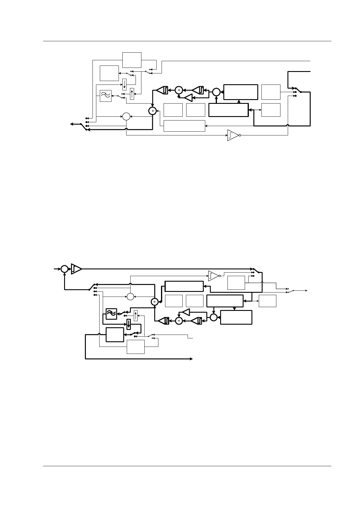
Figure 4 ADM Decoding
The estimator integrators (principal and second) as well as the step size decay (companding integrator)
have programmable time constants. Additionally, the minimum and maximum step height and the depth
of the delay register are programmable via preset values in the DECODE and ENCODE ADM CONTROL
Registers ($D1 and $E1) to support a wide variety of different ADM algorithms including CVSD of
Bluetooth™ version 1.1. The switches in Figures 3 and 4 are controlled by the ENCODER and
DECODER MODE and SETUP Registers ($E0 and $D0). Various signal flows are possible to allow
standard ADM and PCM encoding and decoding as well as transcoding either direction between ADM and
PCM (e.g. Figures 7 and 8). Additionally, several summing options are possible. In the decoder a PCM
and ADM input stream may be summed – note that this requires at least one of the streams to be input
via C-BUS. In the encoder a PCM input stream may be summed with the ADM estimate causing the
encoded ADM bit stream to represent the sum of the analog input and linear PCM stream input over C-
BUS.
5.1.2 PCM Encoding and Decoding
+
ENCODER FEEDBACK
-
PCM TO ADM TRANSCODE FEEDBACK
OFFSET NULLING
REGS $E3 & $E5
ADM
INPUT
REG $E8
ADM OUT
+
ENCODE
SETUP
REG $E0
ADM CTL
REG $E1
DELAY
REGISTER
ADM
OUTPUT
REG $EA
PCM
OUTPUT
REG $E6
PCM
INPUT
REG $E7
1st
2nd
x
ESTIMATOR INTEGRATORS
LINEAR
PCM IN
PROGRAMMABLE
STEP SIZE
CONTROL
LINEAR
PCM OUT
Figure 5 PCM Encoding
The output of the first or principal estimator integrator in Figures 3 and 4 is linear PCM. By decimating
and filtering this signal it is possible to obtain a linear PCM representation, as shown in Figures 5 and 6.
Employing either 8:1 or 4:1 decimation filters provides about 30dB attenuation of out of band quantisation
noise prior to decimation. The ADM coding engine, which suppresses out of band noise by roughly 20dB,
provides (in conjunction with the decimating filter) an overall out of band suppression of approximately
50dB. Using second order ADM at 64kbps with the 8:1 decimation filter provides better than toll quality
linear speech samples. Accordingly, 8k samples/sec linear PCM encoder performance can be enhanced
when the ADM codec second order integrator is enabled and the ADM codec is operated at the maximum
rate. Decoding PCM simply requires interpolation and filtering to compensate for sin(x)/x roll-off of zero
holding the PCM samples. The interpolation ratio can be programmed to 4 or 8.
© 2003 CML Microsystems Plc
7
D/649/2
Share Link: 