AN-6920MR 查看數據表(PDF) - Fairchild Semiconductor
零件编号
产品描述 (功能)
比赛名单
AN-6920MR
Fairchild Semiconductor

AN-6920MR Datasheet PDF : 17 Pages
| |||
AN-6920
Non-Conduction Time of the MOSFET (tOFF)
FAN6920 has a minimum non-conduction time of MOSFET
(5µs), during which turning on the MOSFET is prohibited.
To maximize the efficiency, it is necessary to turn on the
MOSFET at the first valley of MOSFET drain-to-source
voltage at heavy-load condition. Therefore, the MOSFET
non-conduction time at heavy load condition should be
larger than 5µs.
After determining fS.QRmin and tF, the maximum duty cycle is
calculated as:
Dmax
=
VRO
VRO
+ VO.PFC.L
⋅ (1−
f min
S .QR
⋅tF )
(20)
Then, the primary-side inductance is obtained as:
Lm
=
ηQR ⋅
2
(VO . PFC . L
⋅
f min
S .QR
⋅ Dmax
POUT
)
2
(21)
Once Lm is determined, the maximum peak current and
RMS current of the MOSFET in normal operation are
obtained as:
I PK
DS
=
VO.PFC.L ⋅ Dmax
L f min
m S .QR
(22)
I RMS
DS
=
I PK
DS
Dmax
3
(23)
The MOSFET non-conduction time at heavy load and low
line is obtained as:
tOFF .L
=
(1− Dmax )
f min
S .QR
(24)
The MOSFET non-conduction time at heavy load and
higher voltage of PFC output (VO.PFC.H) is obtained as:
tOFF .H
= t ⋅ VV OFF.L
O . PFC . L
O. PFC . H
⋅ VO.PFC.H + VRO
VO.PFC.L + VRO
(25)
To guarantee the first valley switching at high line and
heavy-load condition, tOFF.H should be larger than 5µs.
APPLICATION NOTE
When designing the transformer, the maximum flux density
swing in normal operation (B) as well as the maximum flux
density in transient (Bmax) should be considered. The
maximum flux density swing in normal operation is related
to the hysteresis loss in the core, while the maximum flux
density in transient is related to the core saturation.
The minimum number of turns for the transformer primary
side to avoid over temperature in the core is given by:
N min
P
=
Lm I DS PK
Ae∆B
(26)
where B is the maximum flux density swing in Tesla.
If there is no reference data, use B =0.25~0.30T.
Once the minimum number of turns for the primary side is
determined, calculate the proper integer for NS so that the
resulting NP is larger than Npmin as:
NP
= n⋅ NS
>
N min
P
(27)
The number of turns of the auxiliary winding for VDD is
given as:
N AUX
=
V nom
DD
+
VFA
(VO + VF )
⋅ NS
(28)
where VDDnom is the nominal VDD voltage, the range about
12~20V, and the VFA is forward-voltage drop of VDD diode,
about 1V.
Once the number of turns of the primary winding is
determined, the maximum flux density when the drain
current reaches its pulse-by-pulse current limit level should
be checked to guarantee the transformer is not saturated
during transient or fault condition.
The maximum flux density (Bmax) when drain current
reaches ILIM is given as:
Bmax
= Lm ILIM
Ae NP
< Bsat
(29)
Bmax should be smaller than the saturation flux density.
If there is no reference data, use Bsat =0.35~0.40T.
(Design Example) Setting the minimum frequency is
65kHz and the falling time is 1µs, and assuming
VO.PFC.L=300V:
D max
=
VRO
VRO
+ VO.PFC.L
⋅ (1−
f min
S .QR
⋅tF
)
= 240 ⋅ (1− 70 ×103 ⋅1×10−6 ) = 0.413
240 + 300
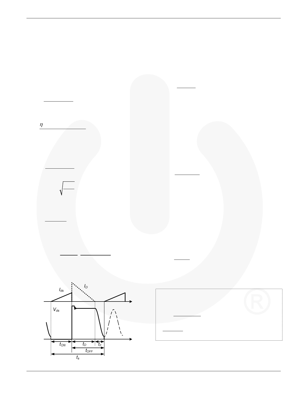
Figure 14. Switching Timing of QR Flyback Converter
© 2010 Fairchild Semiconductor Corporation
Rev. 1.0.0 • March 10, 2011
9
www.fairchildsemi.com
Share Link: