GM431 查看數據表(PDF) - Gamma Microelectronics Inc.
零件编号
产品描述 (功能)
比赛名单
GM431 Datasheet PDF : 14 Pages
| |||
AA
MICROELECTRONICS
Power Management
GM431
2.5V ADJUSTABLE SHUNT REGULATOR
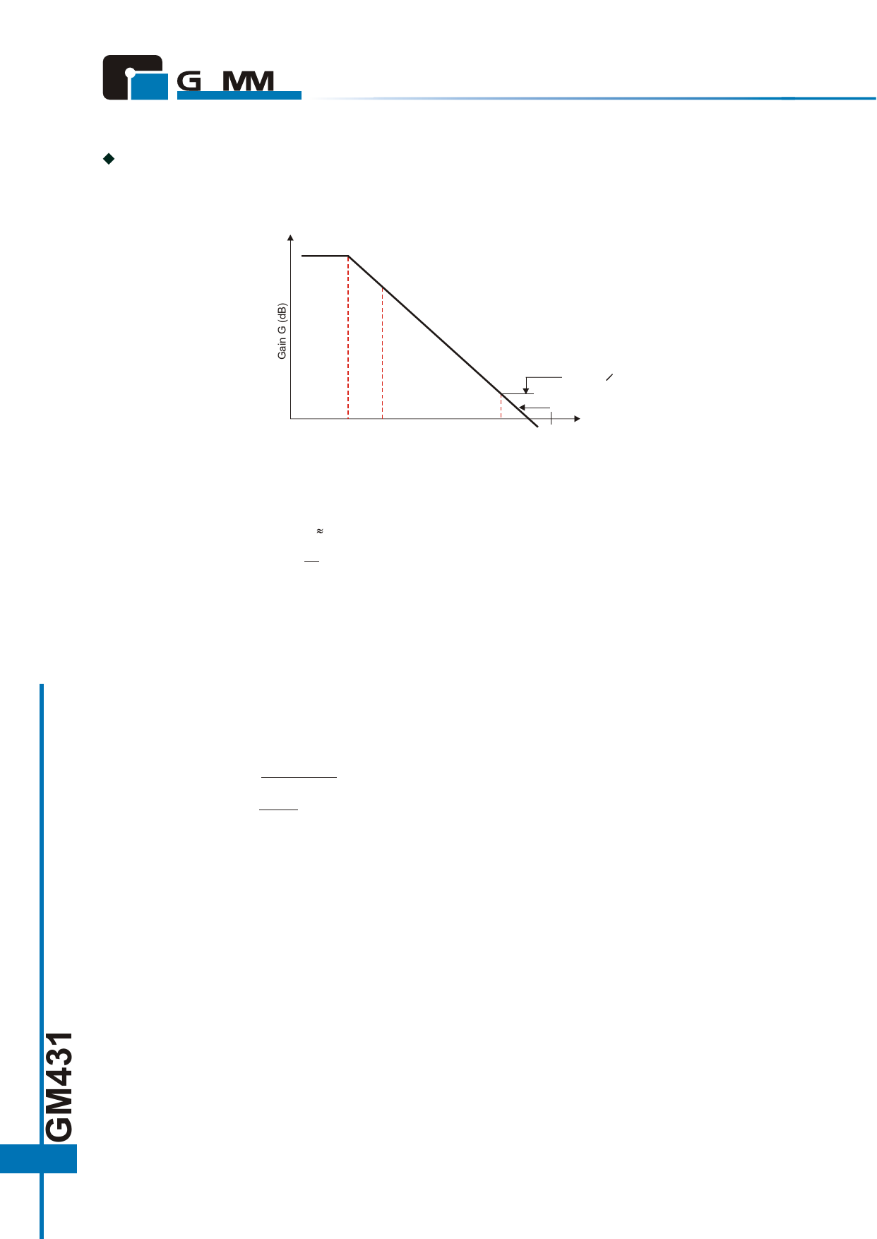
AC Characteristic Determination:
This refers to the determination of the gain frequency characteristic of the shunt regulator as an error amplifier.
Taking the configuration in figure 16, the error amplifier characteristic is as shown in figure 17.
G1
* fosc: PWM switching frequency
When R5= 0
G2
When R5= 0
F1 FAC
F2
Fosc Frequency f (Hz)
Figure 17. GM431 Error Amplification Characteristic
In Figure 17, the following formulas are obtained:
Gain
G1 = G0 50 dB to 60 dB (determined by shunt regulator)
G2 =
R5
R3
Corner frequencies
f1 = 1/(2p C1 G0 R3)
f2 = 1/(2p C1 R5)
G0 is the shunt regulator open-loop gain; this is given by the reciprocal of the reference voltage fluctuation
DVref/DVKA, and is approximately 50 dB.
Practical Example
Consider the example of a photocoupler, with an internal light emitting diode VF = 1.05 V and IF = 2.5 mA,
power supply output voltage V2 = 5 V, and bias resistance R2 current of approximately 1/5 IF at 0.5 mA. If
the shunt regulator VK = 3 V, the following values are found.
5V - 1.05V - 3V
R1= 2.5mA + 0.5mA =316W
1.05V
R2= 0.5mA =2.1 kW
Next, assume that R3 = R4 = 10 kW. This gives a 5 V output. If R5 = 3.3 kW and C1 = 0.022 µF, the
following values are found.
G2 = 3.3 kW / 10 kW = 0.33 times (–10 dB)
f1 = 1 / (2 x p x 0.022 µF x 316 x 10 kW) = 2.3 (Hz)
f2 = 1 / (2 x p x 0.022 µF x 3.3 kW) = 2.2 (kHz)
10
Share Link: 