GM431 查看數據表(PDF) - Gamma Microelectronics Inc.
零件编号
产品描述 (功能)
比赛名单
GM431 Datasheet PDF : 14 Pages
| |||
AA
MICROELECTRONICS
Power Management
GM431
2.5V ADJUSTABLE SHUNT REGULATOR
Design Guide for AC-DCSMPS (Switching Mode Power Supply)
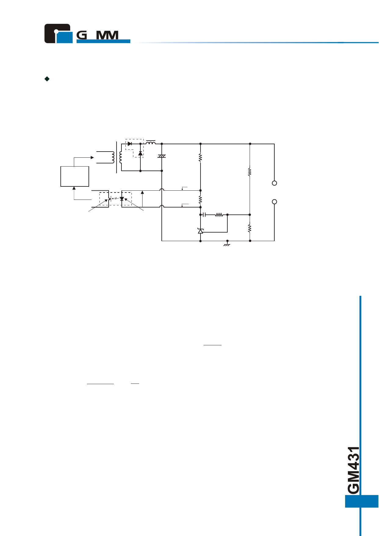
Use of Shunt Regulator in Transformer Secondary side Control
This example is applicable to both forward transformers and flyback transformers. A shunt regulator is used on the secondary
side as an error amplifier, and feedback to the primary side is provided via a photocoupler.
Transformer
GM384X
GM38C4X
SBD
R1
R3
IF
VF
Phototransistor Photocoupler
Light
emitting diode
GM431
IB
R2
VK
C1
R5
REF
Vref
R4
GND
(+)
Output
VO
(-)
Figure 16. Typical Shunt Regulator/ Error Amplifier
Determination of External Costants for the Shunt Regulator
Dc characteristic determination: In figure 16, R1
and R2 are protection resistor for the light emitting
diode in the photocoupler, and R2 is a bypass
resistor to feed IK Minimum, and these are
determined as shown below. The photocoupler
specification should be obtained separately from the
manufacturer. Using the parameters in figure 16, the
following formulas are obtained:
R1 = VO - VF - VK , R 2 = VF
IF +IB
IB
Next, the output voltage can be determined by R3
and R4, and the following formula is obtained:
R3 +R4
VO = R4 X Vref, Verf =2 .5 V Typ
The absolute values of R3 and R4 are determined by
the GM431 reference input current Iref and the AC
characteristics described in the next section. The Iref
value is around 0.7µA Typ.
VK Is the GM431 operating voltage, and is set at
around 3V, taking into account a margin for
fluctuation. R2 is the current shunt resistance for the
light emitting diode, in which a bias current IB of
around 1/5 IF flows.
9
Share Link: 