HFBR-1535 查看數據表(PDF) - HP => Agilent Technologies
零件编号
产品描述 (功能)
比赛名单
HFBR-1535 Datasheet PDF : 19 Pages
| |||
8
Transmitter Electrical/Optical Characteristics 0°C to 70°C unless otherwise specified.
Parameter
Transmitter Output
Optical Power
Output Optical Power
Temperature Coefficient
Peak Emission
Wavelength
Forward Voltage
Forward Voltage
Temperature Coefficient
Effective Diameter
Numerical Aperture
Reverse Input Breakdown
Voltage
Diode Capacitance
Rise Time
Fall Time
Symbol
PT
∆ PT /∆T
λPK
VF
∆VF/∆ T
D
NA
VBR
CO
tr
tf
Min.
-16.5
-14.3
Typ.[5]
-0.85
Max.
-7.6
-8.0
Units
dBm
dBm
%/ °C
Conditions
IFdc = 60 mA
IFdc = 60 mA, 25°C
Ref.
Notes 1, 2
660
nm
1.45 1.67 2.02 V IFdc = 60 mA
-1.37
mV/°C
Fig. 9
1
0.5
5.0 11.0
86
80
40
mm
V IFdc = 10 µA,
TA = 25°C
pF VF = 0, f = MHz
ns 10% to 90%,
ns IF = 60 mA
Note 3
Notes:
1. Measured at the end of 0.5 m standard fiber optic cable with large area detector.
2. Optical power, P (dBm) = 10 Log [P(µW)/1000 µW].
3. Rise and fall times are measured with a voltage pulse driving the transmitter and a series connected 50 Ω load. A wide bandwidth
optical to electrical waveform analyzer, terminated to a 50 Ω input of a wide bandwidth oscilloscope, is used for this response time
measurement.
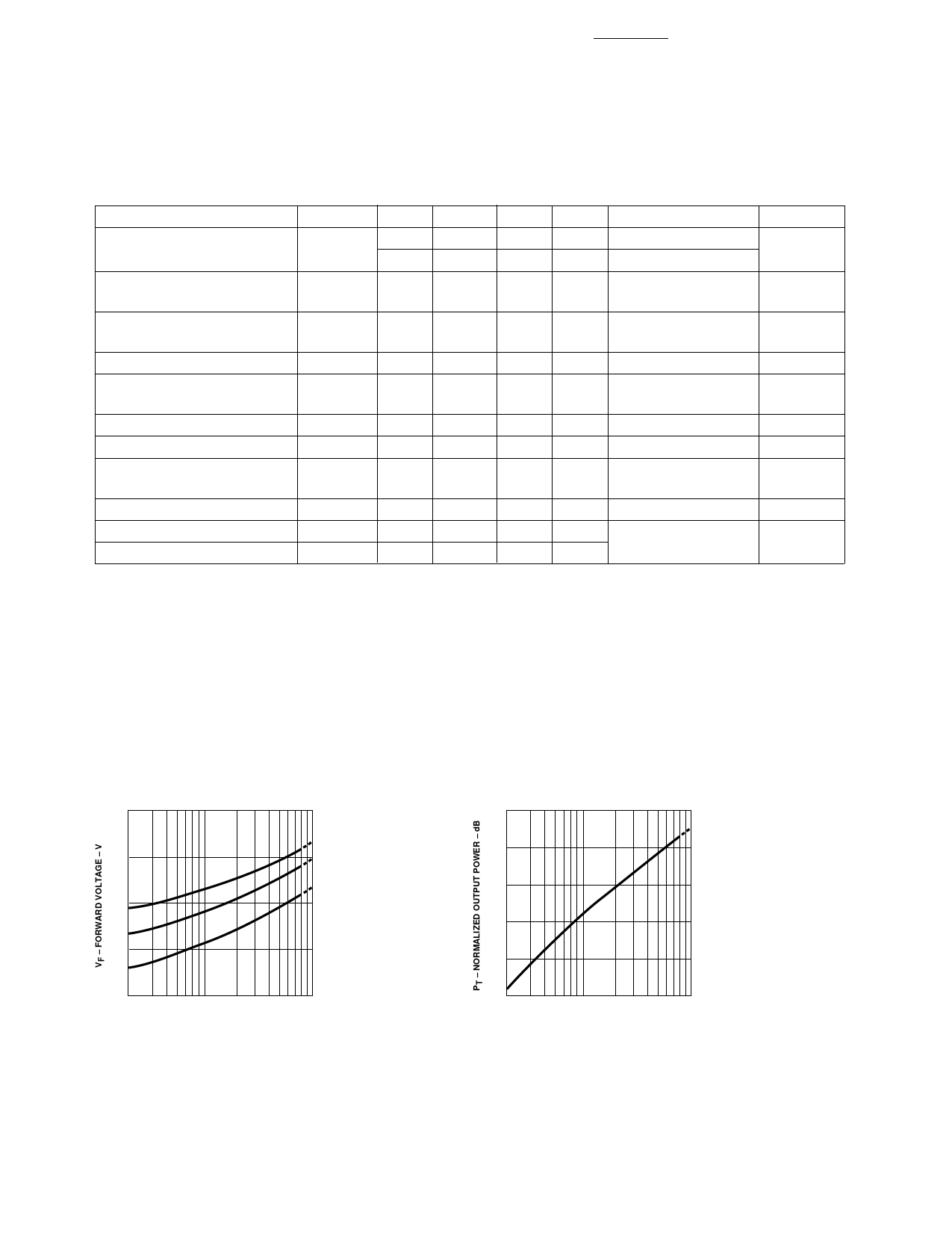
1.8
1.7
0°C
1.6
25°C
1.5
70°C
1.4
2
10
100
IFdc – TRANSMITTER DRIVE CURRENT (mA)
Figure 9. Typical Forward Voltage vs. Drive Current.
5
0
-5
-10
-15
-20
2
10
100
IFdc – TRANSMITTER DRIVE CURRENT (mA)
Figure 10. Normalized Typical Output Power vs. Drive
Current.
Share Link: 