HFBR-1535 查看數據表(PDF) - HP => Agilent Technologies
零件编号
产品描述 (功能)
比赛名单
HFBR-1535 Datasheet PDF : 19 Pages
| |||
9
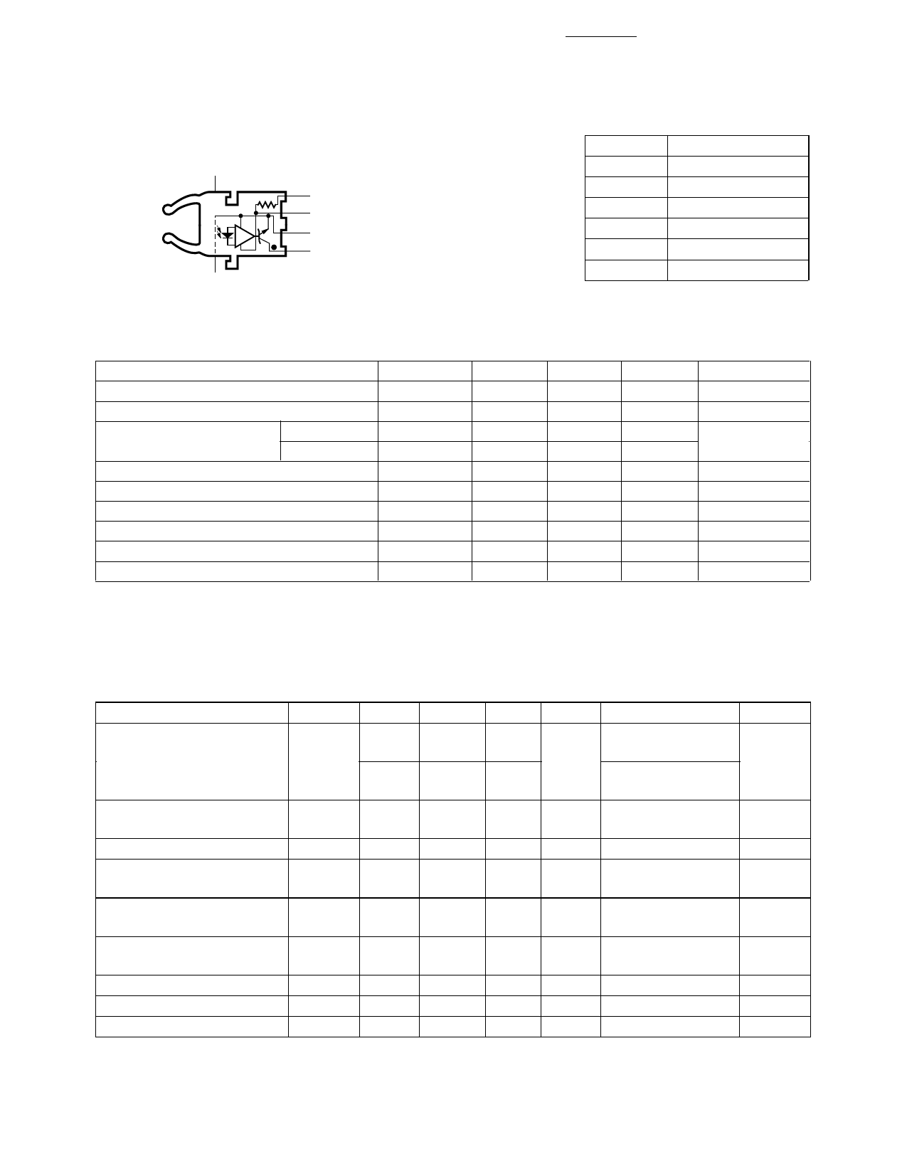
HFBR-25X1 Receiver
DO NOT CONNECT 5
DO NOT CONNECT 8
1000 Ω
4 RL
3 VCC
2 GROUND
1 VO
Pin #
1
2
3
4
5
8
Function
VO
Ground
VCC
RL
Do not connect
Do not connect
Absolute Maximum Ratings
Parameter
Storage Temperature
Operating Temperature
Lead Soldering Cycle
Temp.
Time
Supply Voltage
Output Collector Current
Output Collector Power Dissipation
Output Voltage
Pull-up Voltage
Fan Out (TTL)
Symbol
TS
TA
VCC
IOAV
POD
VO
VP
N
Min.
–40
–40
–0.5
–0.5
–5
Note: Pins 5 and 8 are for mounting and
retaining purposes only. Do not
electrically connect these pins.
Max.
+85
+85
260
10
7
25
40
18
VCC
5
Units
°C
°C
°C
sec
V
mA
mW
V
V
Reference
Note 1
Note 2
Notes:
1. 1.6 mm below seating plane.
2. It is essential that a bypass capacitor 0.01 µF be connected from pin 2 to pin 3 of the receiver. Total lead length between both ends
of the capacitor and the pins should not exceed 20 mm.
Receiver Electrical/Optical Characteristics
0°C to 70°C, 4.75 V ≤ VCC ≤ 5.25 V unless otherwise specified
Parameter
Symbol Min. Typ. Max.
Input Optical Power
Level for Logic “0”
PR(L)
–21.6
–9.5
–21.6
–8.7
Input Optical Power
Level for Logic “1”
High Level Output Current
Low Level Output Current
PR(H)
IOH
VOL
High Level Supply
ICCH
Current
Low Level Supply Current ICCL
Effective Diameter
D
Numerical Aperture
NA
Internal Pull-up Resistor
RL
–43
5
250
0.4
0.5
3.5
6.3
6.2
10
1
0.5
680 1000 1700
Units
dBm
dBm
µA
V
mA
mA
mm
Ω
Conditions
VOL = 0.5 V
IOL = 8 mA
VOL = 0.5 V
IOL = 8 mA, 25°C
VOL = 5.25 V
IOH ≤ 250 µA
VO = 18 V, PR = 0
IOL = 8 mA,
PR = PR(L)MIN
VCC = 5.25 V,
PR = 0
VCC = 5.25 V
PR = -12.5 dBm
Ref.
Notes 1,
2, 4
Note 1
Note 3
Note 3
Note 3
Note 3
Notes:
1. Optical flux, P (dBm) = 10 Log [P (µW)/1000 µW].
2. Measured at the end of the fiber optic cable with large area detector.
3. RL is open.
4. Pulsed LED operation at IF > 80 mA will cause increased link tPLH propagation delay time. This extended tPLH time contributes to
increased pulse width distortion of the receiver output signal.
Share Link: 