MAX7432AEUD 查看數據表(PDF) - Maxim Integrated
零件编号
产品描述 (功能)
比赛名单
MAX7432AEUD Datasheet PDF : 21 Pages
| |||
Standard Definition Video Reconstruction
Filters and Buffers
MAX7432A
13
14
—
—
—
—
PIN
MAX7430
9
10
—
—
—
—
MAX7428
—
2
1
3
5
8
Pin Description (continued)
NAME
OUT1
VCC
INA
INB
SYNCIO
OUT
FUNCTION
Buffer Output 1
+5V Supply Voltage
Video Input A. Use a 0.1µF series input capacitor for proper operation.
Video Input B. Use a 0.1µF series input capacitor for proper operation.
Sync Pulse Input or Output
Buffer Output
0.1μF
D/A
*1MΩ
D/A
ENCODER
0.1μF
*1MΩ
5V
VCC
INA
OUT
MAX7428
REXT
INB
DATA
GND
SYNCIO
75Ω
**220μF
75Ω
**220μF
C1
300kΩ
Z0 = 75Ω
75Ω
Z0 = 75Ω
75Ω
***
10kΩ
SERIAL I/O
5V
SYNC PULSE
IN OR OUT
C1 = 1nF TO 1μF (SEE TABLE 3)
*NEEDED ONLY IN FILTER BYPASS MODE
**OPTIONAL CAPACITOR
***ONLY ONE PULLUP RESISTOR NEEDED PER BUS
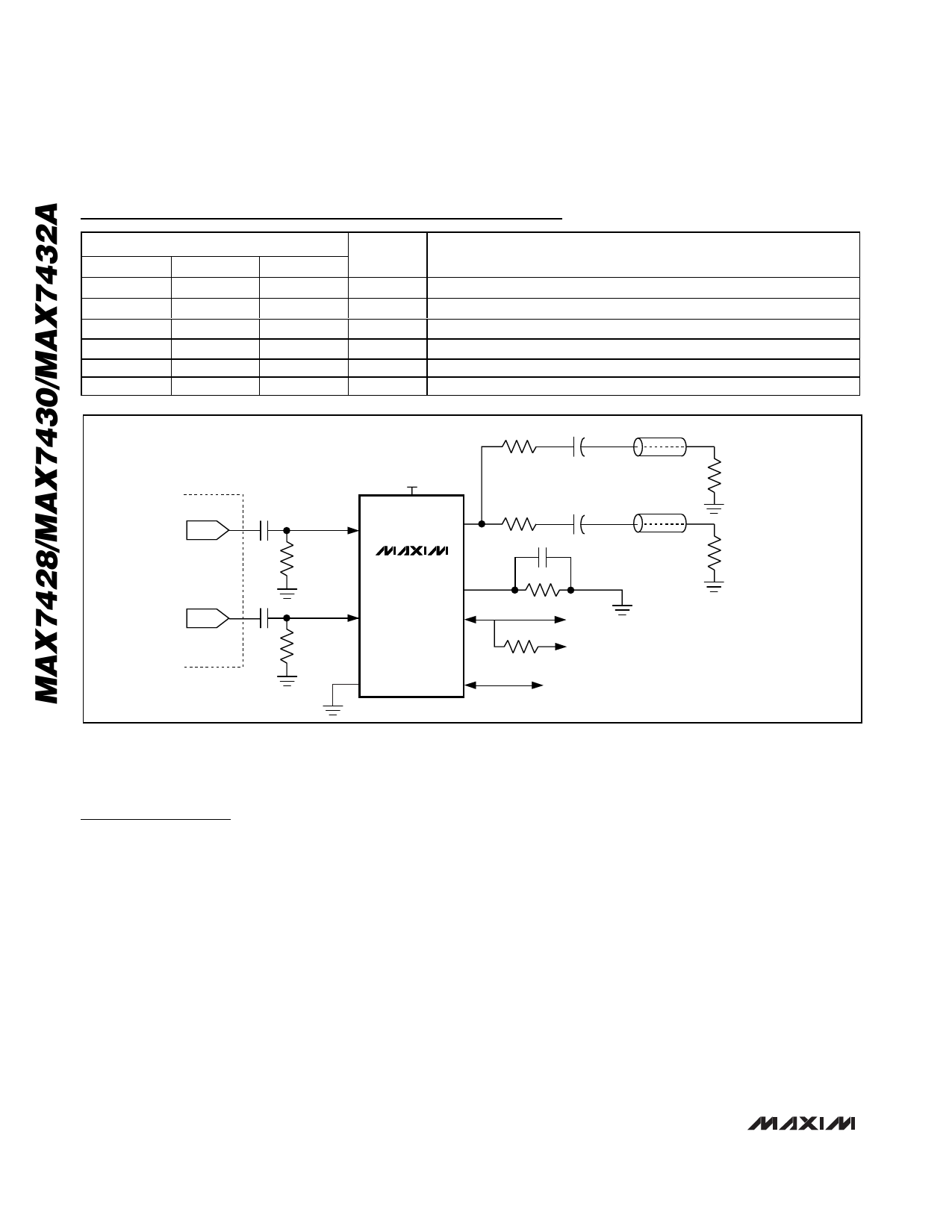
Figure 1. MAX7428 Typical Application Circuit
Detailed Description
The MAX7428/MAX7430/MAX7432A filter and buffer the
outputs of DAC encoder chipsets that process digital
video information in applications such as set-top boxes,
hard-disk recorders, DVD players, recorders, and digi-
tal VCRs. These devices also filter and “clean-up” ana-
log video signals. Each channel in the MAX7428/
MAX7430/MAX7432A includes an input mux to select
the input channel, a 6th-order Sallen-Key filter with four
adjustable high-frequency boost levels, an output
buffer with a 6dB gain, a sync detector and clamp, and
an external resistor to set internal bias levels. Output
disable adds additional multiplexing in a wired-OR con-
figuration. Filter bypass, in conjunction with the two
inputs, can be used to provide filtered and unfiltered
video signal processing. Maxim’s Single Pin Bus
(MSPB) interface controls all of the above features. An
external capacitor is used to assign each device a
unique address that allows control of up to 16 devices
on the same bus. Typical application circuits for the
MAX7428/MAX7430/MAX7432A are shown in Figures 1,
2, and 3.
Input Considerations
Use a 0.1µF ceramic capacitor to AC-couple the input
to the MAX7428/MAX7430/MAX7432A. This input
capacitor stores a DC level to level-shift the input signal
to an optimal point between VCC and GND. The ABSEL
bit on the Control Register sets which channel (IN_A or
IN_B) is selected (Control Register section). The IN_A
and IN_B inputs have a typical input resistance of
50kΩ.
6 _______________________________________________________________________________________
Share Link: 