MSM7617 查看數據表(PDF) - Oki Electric Industry
零件编号
产品描述 (功能)
比赛名单
MSM7617 Datasheet PDF : 29 Pages
| |||
¡ Semiconductor
MSM7617
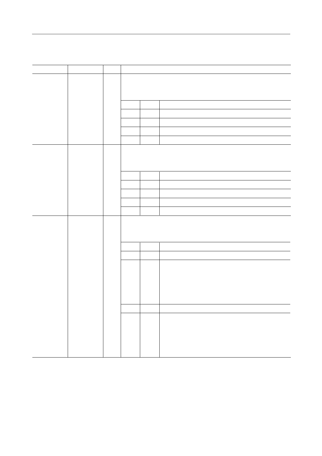
PIN DESCRIPTIONS (Continued)
Pin
Symbol Type
Description
24
SG11
I S output gain control pins for channel 1 (refer to the block diagram).
25
SG10
These pins amplify the output level of SOUT. The gain level can be set even
during the echo canceler disable mode.
SG11 SG10 Gain Level
0
0 0 dB
0
1 +6 dB
1
0 +12 dB
1
1 Not used
26
SA11
I S input attenuator control pins for channel 1 (refer to the block diagram).
27
SA10
These pins attenuate the input level of SIN. Use them if ERL is large.
The attenuation level can be set even during the echo canceler disable mode.
SA11 SA10 Attenuation Level
0
0 0 dB
0
1 –6 dB
1
0 –12 dB
1
1 Not used
29
RGC11
I R input level control pins for channel 1 (refer to the block diagram).
30
RGC10
Excessive input (PCM level is at maximum value) causes a malfanction.
Use these pins when there is a possibility of excessive input.
RGC11 RGC10 Level Control Mode
0
0 Off
0
1 GC: On (control level = –20 dBm0)
By the R gain controller, levels from –20 to –11.5 dBm0 will
be suppressed to –20 dBm0 and those above –11.5 dBm0 will
always be attenuated by 8.5 dB. This is effective to prevent
excessive input and howling for hands-free applications.
1
0 Inhibited
1
1 ±6LR: On
Applies –6 dB to excessive inputs using the level adjuster
provided on R and S I/O. Since +6 dB also is applied at the
output, the total level will not change, making this effective
against line echo.
9/28
Share Link: 