MT8920 查看數據表(PDF) - Mitel Networks
零件编号
产品描述 (功能)
比赛名单
MT8920 Datasheet PDF : 24 Pages
| |||
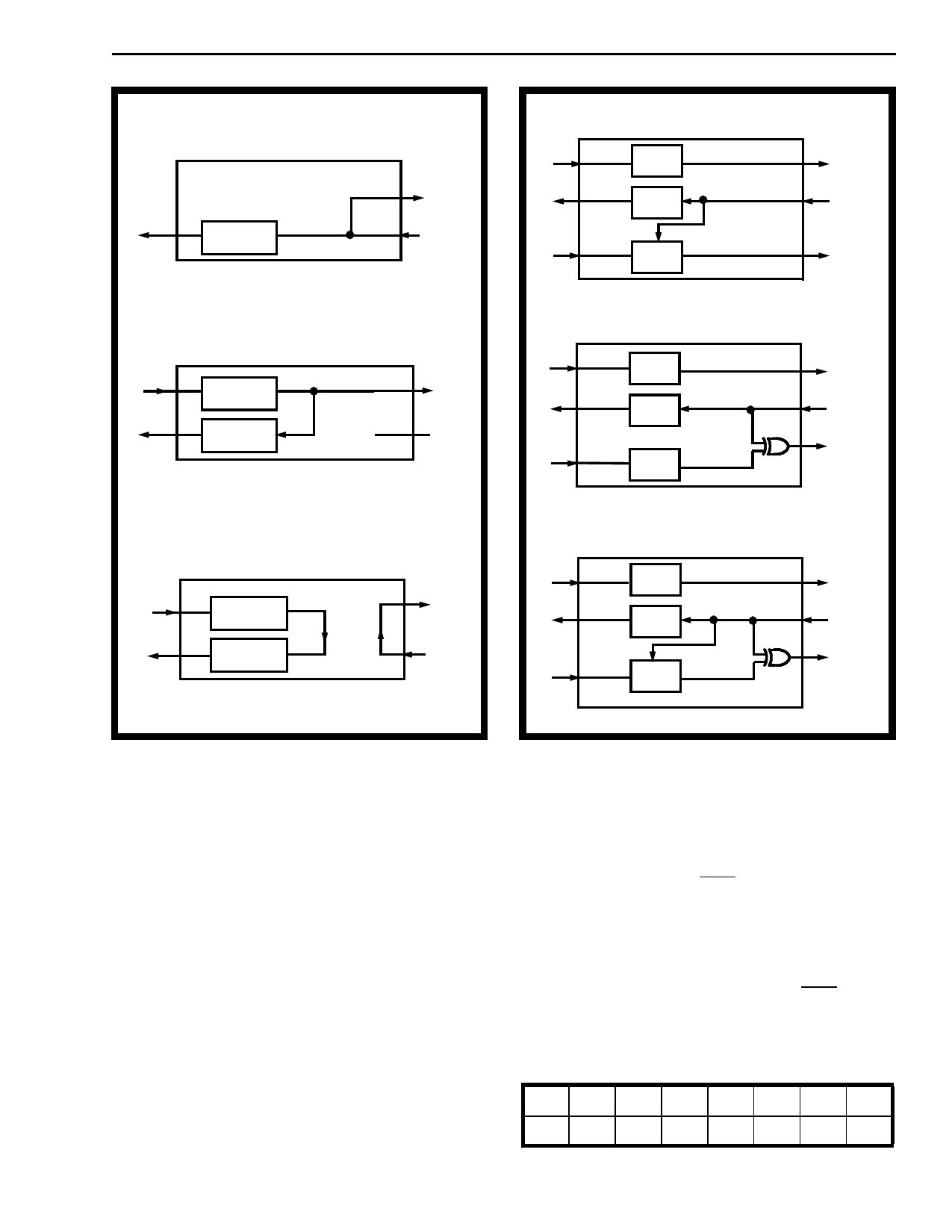
CMOS MT8920B
Control Register 2
Bits D1 = 0, D0 = 1
µP
Rx0
a)
Control Register 2
Bits D1 = 1, D0 = 0
Tx0
µP
Rx0
b)
Control Register 2
Bits D1 = 1, D0 = 1
Tx0
µP
Rx0
STo0
STi0
STo0
STi0
STo0
STi0
c)
Figure 5 - Loopback Configurations
Interrupt Mask Register (1/2): In static mode the
contents of this register masks bits in the Match Byte
Register that are ’don’t care’ bits
1 - bit masked
0 - bit not masked
In dynamic mode, each bit in this register and the
corresponding bit in the Match Byte Register define
what type of dynamic interrupt is selected. (Refer to
Table 5.)
Interrupt Flag Register (1/2): In static mode
the least significant bit in this register is set to 1 to
flag the corresponding path in which the interrupt
occurs.
In dynamic mode this register sets the bits which
reflect the position of the bits in the corresponding
Interrupt Register which caused the interrupt.
Control Register 2
Bits D3 = 0, D2 = 1
Tx0
µP
Rx0
STo0
STi0
Tx1
1 Frame Delay
a)
Control Register 2
Bits D3 = 1, D2 = 0
Tx0
µP
Rx0
Tx1
b)
Control Register 2
Bits D3 = 1, D2 = 1
STo1
STo0
STi0
STo1
Tx0
µP
Rx0
STo0
STi0
Tx1
1 Frame Delay
STo1
c)
Figure 6 - STo1 Configurations
Interrupt Vector Register
This register shown in Figure 7 is common to both
interrupt paths and stores an 8 bit vector number
which will be output on the data bus when
Interrupt Acknowledge (IACK) is asserted. Bits
labelled V2 - V7 are stored by the controlling µP.
Bits IRQ1 and IRQ2 are set by the STPA to indicate
which path caused the interrupt. This creates unique
vectors which are used by the µP to vector to
interrupt service routines. This feature may be
bypassed by simply not asserting IACK during
interrupt acknowledged.
D7 D6 D5 D4 D3 D2 D1 D0
V7 V6 V5 V4 V3 V2 IRQ2 IRQ1
Figure 7 - Interrupt Vector Registers
3-11
Share Link: 