PDI1394L21 查看數據表(PDF) - Philips Electronics
零件编号
产品描述 (功能)
比赛名单
PDI1394L21 Datasheet PDF : 52 Pages
| |||
Philips Semiconductors
1394 full duplex AV link layer controller
Preliminary specification
PDI1394L21
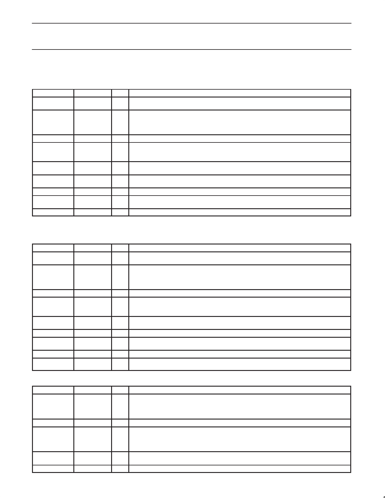
9.2 AV Interface 1
NOTE: This AV interface may be configured to transmit or receive according to the condition of “DIRAV1” bit in GLOBCSR register
(0X018)—default is transmit.
PIN No.
PIN SYMBOL I/O
NAME AND FUNCTION
77, 76, 75, 74,
71, 70, 69, 68
AV1 D[7:0]
I/O Audio/Video Data 7 (MSB) through 0. Byte-wide interface to the AV layer 1.
External application clock. Rising edge active. This pin can be programmed to output the
58
AV1CLK
I/O
application clock. Depending on the configuration of AV Port 1 as transmitter or receiver, the
output enable is located in the ITXPKCTL register (address 0x020) or IRXPKCTL register
(address 0x040).
57
AV1SYNC I/O Start of packet indicator; should only be used when AV1VALID is active.
Programmable frame sync, can be set to input. Frame sync input used for Digital Video (DV). The
59
AV1FSYNC I/O signal is time stamped and transmitted in the SYT field of ITXHQ2. Frame sync output. Signal is
derived from SYT field of IRXHQ2.
56
AV1ENDPCK
I
End of application packet indication from data source. Required only if input packet is not multiple
of 4 bytes. It can be tied LOW for data packets that are 4*N in size.
60
AV1ENKEY
I/O
Encryption key state. Indicates state “1” or “0” of encryption key which matches present port data
during receive mode. Used to input key state during transmit mode.
61
AV1VALID I/O Indicates data on AV1 D [7:0] is valid.
53
AV1ERR0
O
CRC error, indicates bus packet containing AV1 D [7:0] had a CRC error, the current AV packet is
unreliable.
52
AV1ERR1
O Sequence Error. Indicates at least one source packet was lost before the current AV1 D [7:0] data.
9.3 AV Interface 2
NOTE: This AV interface may be configured to transmit or receive according to the condition of “DIRAV1” bit in GLOBCSR register—default is
receive.
PIN No.
PIN SYMBOL I/O
NAME AND FUNCTION
98, 97, 96, 95,
92, 91, 90, 89
AV2 D[7:0]
I/O Audio/Video Data 7 (MSB) through 0. Byte-wide interface to the AV layer 2.
External application clock. Rising edge active. This pin can be programmed to output the
84
AV2CLK
I/O
application clock. Depending on the configuration of AV Port 2 as transmitter or receiver, the
output enable is located in the ITXPKCTL register (address 0x020) or IRXPKCTL register
(address 0x040).
83
AV2SYNC I/O Start of packet indicator; should only be used when AV2VALID is active.
Programmable frame sync, can be set to input or output. Frame sync input used for Digital Video
85
AV2FSYNC I/O (DV). The signal is time stamped and transmitted in the SYT field of ITXHQ2. Frame sync output.
Signal is derived from SYT field of IRXHQ2.
82
AV2ENDPCK
I
End of application packet indication from data source. Required only if input packet is not multiple
of 4 bytes. It can be tied LOW for data packets that are 4*N in size.
86
AV2VALID I/O Indicates data on AV2 D [7:0] is valid.
81
AV2ERR0
O
CRC error, indicates bus packet containing AV2 D [7:0] had a CRC error, the current AV packet is
unreliable.
80
AV2ERR1
O Sequence Error. Indicates at least one source packet was lost before the current AV2 D [7:0] data.
99
AV2ENKEY
I/O
Encryption key state. Indicates state “1” or “0” of encryption key which matches present port data
during receive mode. Used to input key state during transmit mode.
9.4 Phy Interface
PIN No.
PIN SYMBOL I/O
NAME AND FUNCTION
43, 42, 41, 40,
37, 36, 35, 34
PHY D[0:7]
Data 0 (MSB) through 7 (NOTE: To preserve compatibility to the specified Link-Phy interface of
I/O
the IEEE 1394–1995 standard, Annex J, bit 0 is the most significant bit). Data is expected on
PHY D[0:1] for 100Mb/s, PHY D[0:3] for 200Mb/s, and PHY D[0:7] for 400Mb/s. See IEEE
1394–1995 standard, Annex J for more information.
47, 46
PHY CTL[0:1] I/O Control Lines between Link and Phy. See 1394 Specification for more information.
Isolation mode. This pin is asserted (LOW) when an Annex J type isolation barrier is used.
48
ISO_N
I
See IEEE 1394–1995 Annex J. for more information. When tied HIGH, this pin enables internal
bushold circuitry on the affected PHY interface pins (see below). Active bushold circuits allow
either the direct connection to PHY pins or the use of the single capacitor isolation mode.
54
LREQ
O
Link Request. Bus request to access the PHY. See IEEE 1394–1995 standard, Annex J for more
information. (Used to request arbitration or read/write PHY registers).
55
SCLK
I System clock. 49.152MHz input from the PHY (the PHY-LINK interface operates at this frequency).
1999 Aug 06
6
Share Link: 