SC1144 查看數據表(PDF) - Semtech Corporation
零件编号
产品描述 (功能)
比赛名单
SC1144 Datasheet PDF : 11 Pages
| |||
PROGRAMMABLE, HIGH PERFORMANCE
MULTI-PHASE, PWM CONTROLLER
SC1144
Preliminary - August 24, 1999
ERROR AMPLIFIER CONT.
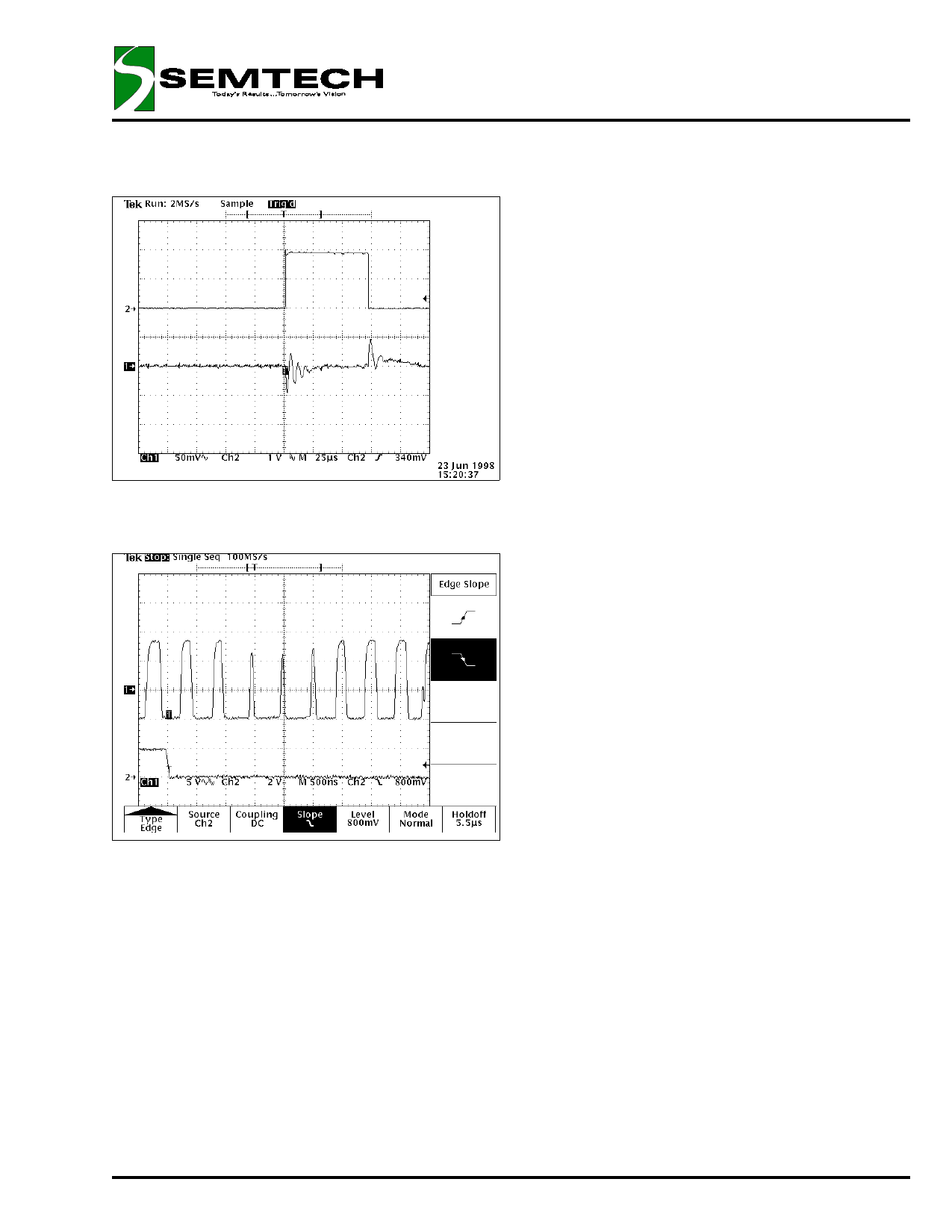
Fig. 2: Transient response, Top trace, Current sense
8A/div @ 30A/usec. Bottom trace, VOUT.
Fig. 3: Top Trace, Gate drive responding to removal of
transient load. Bottom trace, Load current transient
16A/div.
BANDGAP REFERENCE/SOFT START
The precision internal bandgap reference provides a
stable, temperature compensated 2.05 V reference for
the error amplifier’s non-inverting input, the DACREF for
the VID digital to analog converter, the under-voltage
lock-out circuitry as well as the reference for the Bias
generator current sources. The error amplifiers non-
inverting input is connected to the bandgap reference
through a 3 kohm resistor, which is also externally con-
nected to a soft-start capacitor via the BGOUT pin. Upon
application of power, the non-inverting input of the er-
ror amplifier is held low for a short time allowing for the
decoder and PWM controller to settle. This prevents
any harmful output voltage overshoots upon start up or
after a converter shut-down (as a result of over-current
or the enable pin pulled low). The non-inverting input
then ramps up according to the RC time constant al-
lowing gradual rise of output voltage.
ISOLATED FEEDBACK GROUND
The feedback ground pin on the SC1144, FBG, is iso-
lated from the GND. The maximum voltage between
the two pins is set by the ESD diode forward voltage
drop. This allows the SC1144 to be configured for re-
mote sensing thus compensating for wiring and con-
nector voltage drops at high currents or during tran-
sients. Remote sensing is typically implemented by
using differential amplifiers. The use of this feature on
the SC1144 eliminates the need for additional compo-
nents.
OVER-CURRENT COMPARATOR
The SC1144 has an internal over-current comparator
designed to sense current in the input supply path.
The comparator inputs have a high common voltage
range thus allowing operation under all possible volt-
age/current combinations. The output of the compara-
tor pulls the BGOUT (soft start) pin low thus disabling the
error amplifier and causing the PWM outputs to enter
minimum duty cycle mode.
SYNCHRONOUS VS. ASYNCHRONOUS MODE
The SC1144 can be configured to drive Synchrounous
MSOFET drivers, such as the SC1405 for higher effi-
ciency. Refer to SC1405 datasheet for example de-
signs.
COMPONENT SELECTION AND LAYOUT CONSID-
ERATIONS
Care must be taken in component selection and PCB
layout in high frequency power appliactions. Refer to
SC1144EVB user manual for more application informa-
tion on component selection and layout guidlines as
well as example Artwork and Bill of materials.
The SC1144 is patent pending
© 1999 SEMTECH CORP.
10
652 MITCHELL ROAD NEWBURY PARK CA 91320
Share Link: 