SC1144 查看數據表(PDF) - Semtech Corporation
零件编号
产品描述 (功能)
比赛名单
SC1144 Datasheet PDF : 11 Pages
| |||
PROGRAMMABLE, HIGH PERFORMANCE
MULTI-PHASE, PWM CONTROLLER
SC1144
Preliminary - August 24, 1999
THEORY OF OPERATION
FUNCTIONAL DESCRIPTION
The SC1144 is a programmable, high performance,
multi-phase controller designed for the most demand-
ing DC/DC converter applications in which transient
response, space, input ripple current and component
form factor and cost are paramount. The SC1144
based dc/dc converter consists of four asynchronous
converters. The gate drives to the converters are alter-
nated sequentially by the SC1144 allowing equal shar-
ing of the load current among the stages. The high
clock frequency allows for smaller inductor value and
miniature surface mount, low inductance output capaci-
tors. Since each stage has ¼ the output current, the
conduction losses in each stage is reduced by a factor
of 1/16. Precision active trimming ensures 1% match-
ing of duty cycles among phases, thus ensuring the
heat and component stress is shared equally. This al-
lows use of lower cost components in each phase and
virtual elimination of heat sinks.
time. The ramps are then compared to the error ampli-
fier output at the high speed PWM comparator inputs.
The oscilator master clock frequency is programmed as
follows:
Clock Freq=(8.2K/Rref)*8Mhz
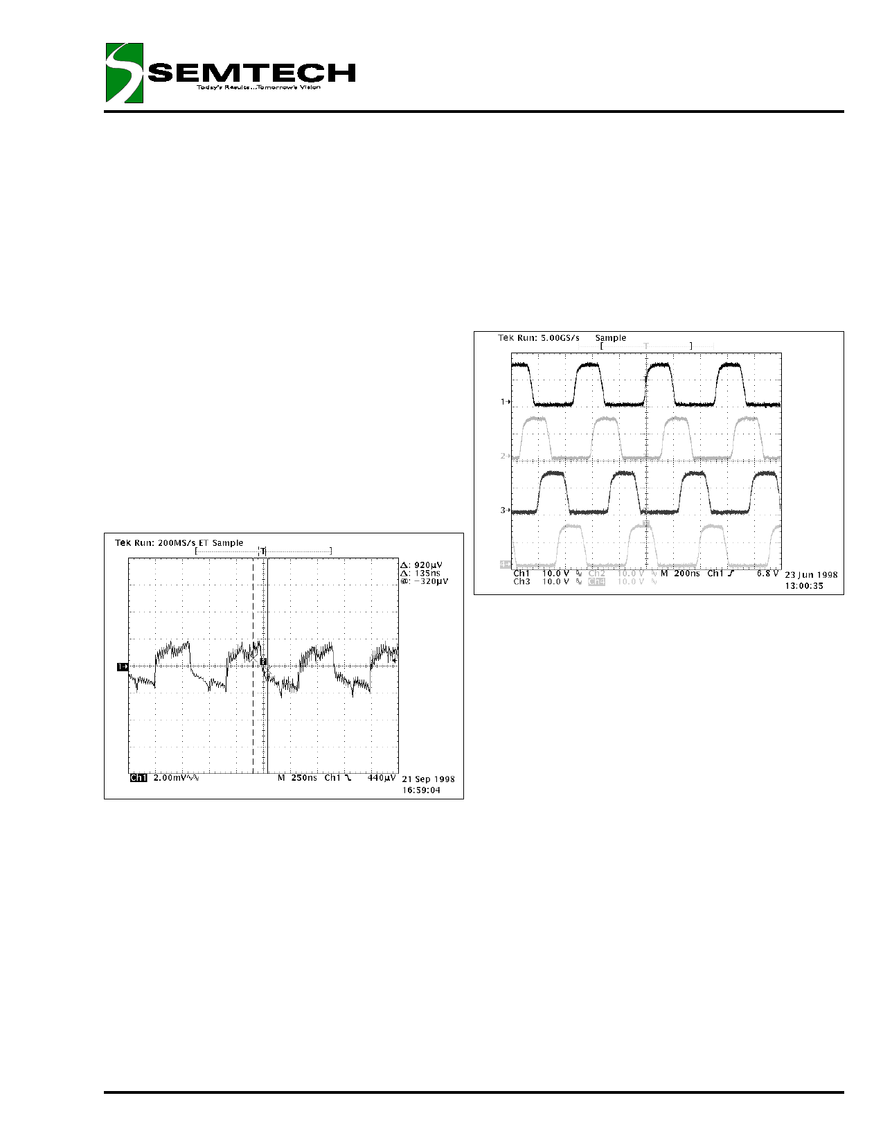
Fig. 1: The four Gate Drives firing 90° out of phase.
VOUT = 2.0V, IOUT = 10A
Fig. 4: VOUT Ripple, VOUT = 2.0V, IOUT = 30A
DECODER/BIAS GENERATOR/PWM CONTROLLER
The 8 MHz clock is divided down to 2 MHz for four
phase operation by the clock decoder. The start of the
output pulses are time shifted 90 degrees by the de-
coder with respect to each other. The Bias Generator
generates the ramps to each phase by a precision
trimmed current source and on-chip capacitors. The
decoder, which is synchronized to the bias generator
via the master clock, phase shifts the ramps and en-
ables the PWM controller sequentially. A resistor from
RREF pin to FBG programs the frequency and ramp
ERROR AMPLIFIER
At the heart of the controller is an ultra-fast, transcon-
ductance error amplifier. Since the output inductor val-
ues can be selected to be a minimum, usually less than
a micro-Henry, the delays due to inductor ramp time are
minimized during transient load recovery. The higher
frequency of operation also allows use of much smaller
capacitance on the output. This means that the dc/dc
converter output capacitors “hold Time” is less. The er-
ror amplifier must therefore respond extremely fast
“Recover the Fort” after a transient. The SC1144 error
amplifier recovers to its normal duty cycle after applica-
tion of a full load transient within 2 usec maximum,
(largely dependant on input and output capacitance) and
usually within 1usec. This minimizes undershoot and
overshoot during application of a transient. Operation at
high frequency minimizes the output inductor thus allow-
ing faster current ramp to the output capacitors.
The effective gain of the error amplifier stays constant in
both VID ranges, keeping the loop gain constant regard-
less of output voltage range.
The SC1144 is patent pending
© 1999 SEMTECH CORP.
9
652 MITCHELL ROAD NEWBURY PARK CA 91320
Share Link: 