SPT7938 查看數據表(PDF) - Cadeka Microcircuits LLC.
零件编号
产品描述 (功能)
比赛名单
SPT7938 Datasheet PDF : 10 Pages
| |||
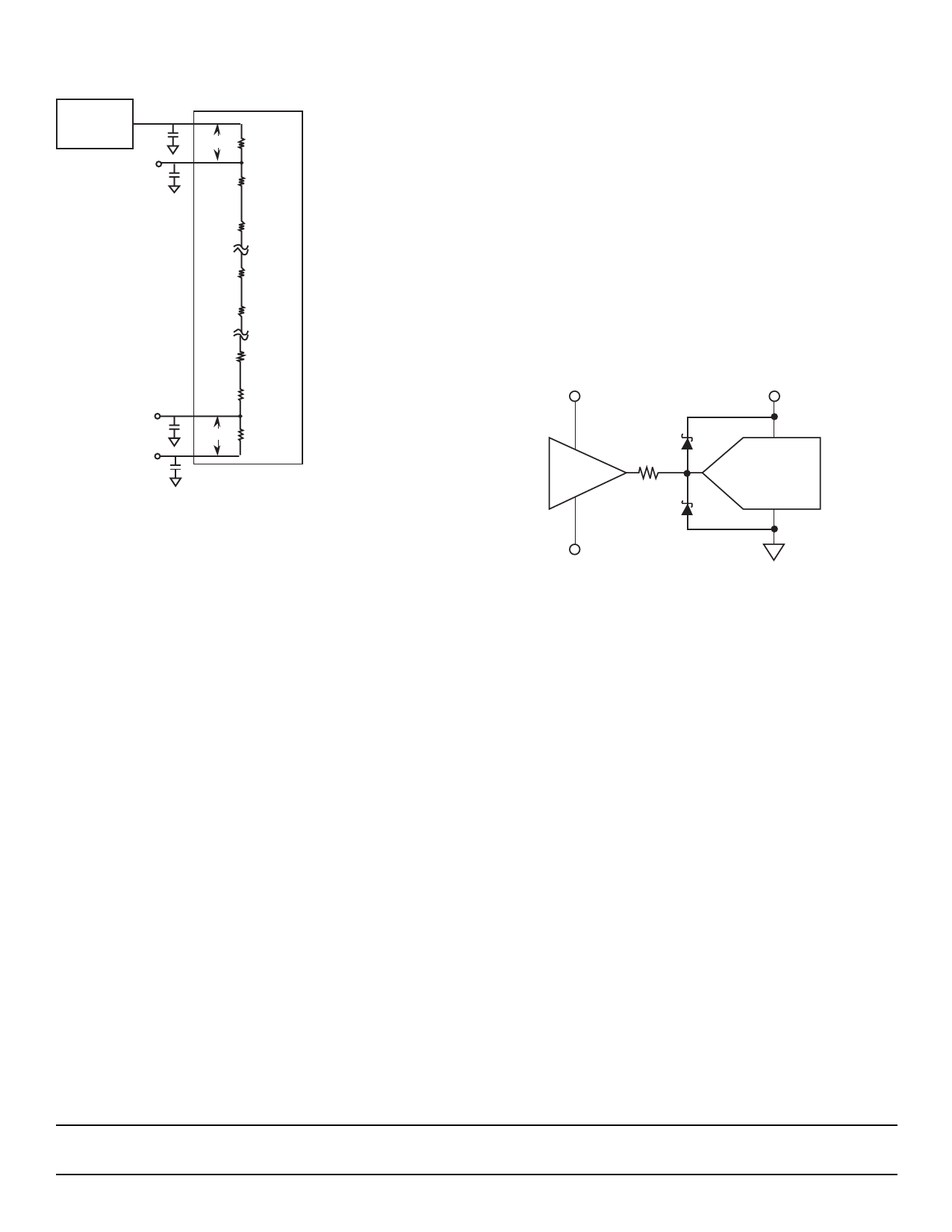
Figure 4 – Simplified Reference Ladder Drive Circuit
Without Force/Sense Circuit
+4.0 V
External
Reference
VRHS
(+3.98 V)
21 mV R/2
R
R
VRLS
(0.050 V)
VRLF (AGND)
0.0 V
R
R
R
R
50 mV R/2
R=30 Ω (typ)
All capacitors are 0.01 µF
In cases in which wider variations in offset and gain can be
tolerated, VRef can be tied directly to VRHF and AGND can
be tied directly to VRLF as shown in figure 4. Decouple force
and sense lines to AGND with a 0.01 µF capacitor (chip cap
preferred) to minimize high-frequency noise injection. If this
simplified configuration is used, the following considerations
should be taken into account:
The reference ladder circuit shown in figure 4 is a simplified
representation of the actual reference ladder with force and
sense taps shown. Due to the actual internal structure of the
ladder, the voltage drop from VRHF to VRHS is not equivalent
to the voltage drop from VRLF to VRLS.
Typically, the top side voltage drop for VRHF to VRHS will
equal:
VRHF – VRHS = 0.5% of (VRHF – VRLF) (typical),
and the bottom side voltage drop for VRLS to VRLF will equal:
VRLS – VRLF = 1.25% of (VRHF – VRLF) (typical).
Figure 4 shows an example of expected voltage drops for a
specific case. VREF of 4.0 V is applied to VRHF and VRLF is
tied to AGND. A 21 mV drop is seen at VRHS (= 3.98 V) and
a 50 mV increase is seen at VRLS (= 0.050 V).
ANALOG INPUT
VIN is the analog input. The input voltage range is from VRLS
to VRHS (typically 4.0 V) and will scale proportionally with re-
spect to the voltage reference. (See the Voltage Reference
section.)
The drive requirements for the analog inputs are very mini-
mal when compared to most other converters due to the
SPT7938’s extremely low input capacitance of only 20 pF
and very high input resistance in excess of 25 kΩ.
The analog input should be protected through a series resis-
tor and diode clamping circuit as shown in figure 5. To pre-
vent possible latch-up condition, the power supplies must
be powered up before the input is applied.
Figure 5 – Recommended Input Protection Circuit
+V
AVDD
Buffer
D1
47 Ω
D2
ADC
–V
D1 = D2 = Hewlett Packard HP5712 or equivalent
CALIBRATION
The SPT7938 uses a user-transparent, auto-calibration
scheme to ensure 12-bit accuracy over time and tempera-
ture. Gain and offset errors are continually adjusted to 12-bit
accuracy during device operation.
Upon powerup, the SPT7938 begins its calibration algo-
rithm. In order to achieve the calibration accuracy required,
the offset and gain adjustment step size is a fraction of a 12-
bit LSB. Since the calibration algorithm is an oversampling
process, a minimum of 10,000 clock cycles are required.
This results in a minimum calibration time upon power-up of
250 µsec (for a 40 MHz clock). Once calibrated, the
SPT7938 remains calibrated over time and temperature.
Since the calibration cycles are initiated on the rising edge
of the clock, the clock must be continuously applied for the
SPT7938 to remain in calibration.
SPT7938
7
5/24/00
Share Link: 