LA7945N 查看數據表(PDF) - SANYO -> Panasonic
零件编号
产品描述 (功能)
比赛名单
LA7945N Datasheet PDF : 9 Pages
| |||
LA7945N
Test Conditions
Parameter
Symbol
Test point
Test method
Horizontal pull-in range
fHPULL
Pins 2 and 10
Vary the frequency fH of the input signal and measure the point where
the phase of pins 2 and 10 locks using an oscilloscope.
Horizontal free-running frequency
fHFREE Pin 10
Use a frequency counter to measure the frequency when there is no
signal.
Input clamping voltage
H LOCK filter threshold level
VCLMP Pin 17
VLOCKTH Pin 7
Measure the pedestal level with an oscilloscope.
Measure the voltage at which pin 7 goes high by applying a DC
voltage to pin 8 and varying that voltage.
High level
Synchronization separation output
Low level
H LOCK filter
High level
Low level
Data output
High level
Low level
Clock output
High level
Low level
High level
21H output
Low level
Pulse width
High level
O/E output
Low level
Pulse width
High level
Horizontal pulse output
Low level
Pulse width
High level
Vertical pulse output
Low level
Pulse width
Input signal level
VSYNCH
VSYNCL
VLOCKH
VLOCKL
VDATAH
VDATAL
VCLKH
VCLKL
V21HH
V21HL
V21HW
VOEH
VOEL
VOEW
VHSH
VHSL
VHSW
VRSTH
VRSTL
VRSTW
VIN
Pin 2*1
Pin 7*1
Pin 3*1, 2
Pin 5*1, 2
Pin 1*1
Pin 6*1
Pin 10*1
Pin 9*1
Each of pins 1,
3, 5, and 6*2
Measure the pin 2 high and low levels with an oscilloscope.
Measure the pin 7 high and low levels with an oscilloscope.
Measure the pin 3 high and low levels with an oscilloscope.
Measure the pin 5 high and low levels with an oscilloscope.
Measure the pin 1 high and low levels and the length of the high level
period with an oscilloscope.
Measure the pin 6 high and low levels and the length of the high level
period with an oscilloscope.
Measure the pin 10 high and low levels and the length of the high level
period with an oscilloscope.
Measure the pin 9 high and low levels and the length of the high level
period with an oscilloscope.
Vary the signal level input to pin 17, and confirm that the pin 1, 3, 5,
and 6 outputs are operating correctly.
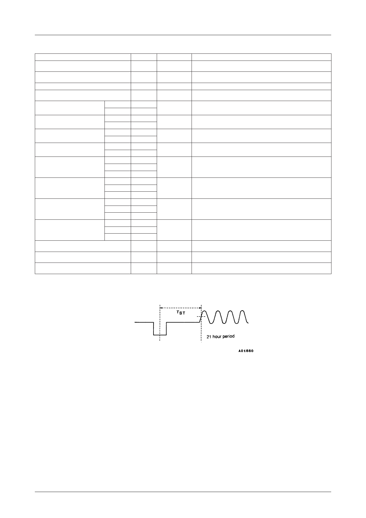
CLK-RUN-IN start time
TST
Each of pins 1, Vary the time between SYNC and CLK-RUN-IN, and confirm that the
3, 5, and 6*2, 3 pin 1, 3, 5, and 6 outputs are operating correctly.
Current drain
ICC
Pin 16*2
Connect a current meter to pin 16, and measure the current during
decoding.
Note : 1. Connect a 20kΩ resistor between the pin being measured and VCC, and also connect a 20kΩ from that measurement pin to GND.
2. During measurement, this pin carries the closed caption encoded signal.
3. Time TST is shown in the figure below.
No.4616–3/9
Share Link: 