UTCMC34118 查看數據表(PDF) - Unisonic Technologies
零件编号
产品描述 (功能)
比赛名单
UTCMC34118 Datasheet PDF : 13 Pages
| |||
UTCMC34118 LINEAR INTEGRATED CIRCUIT
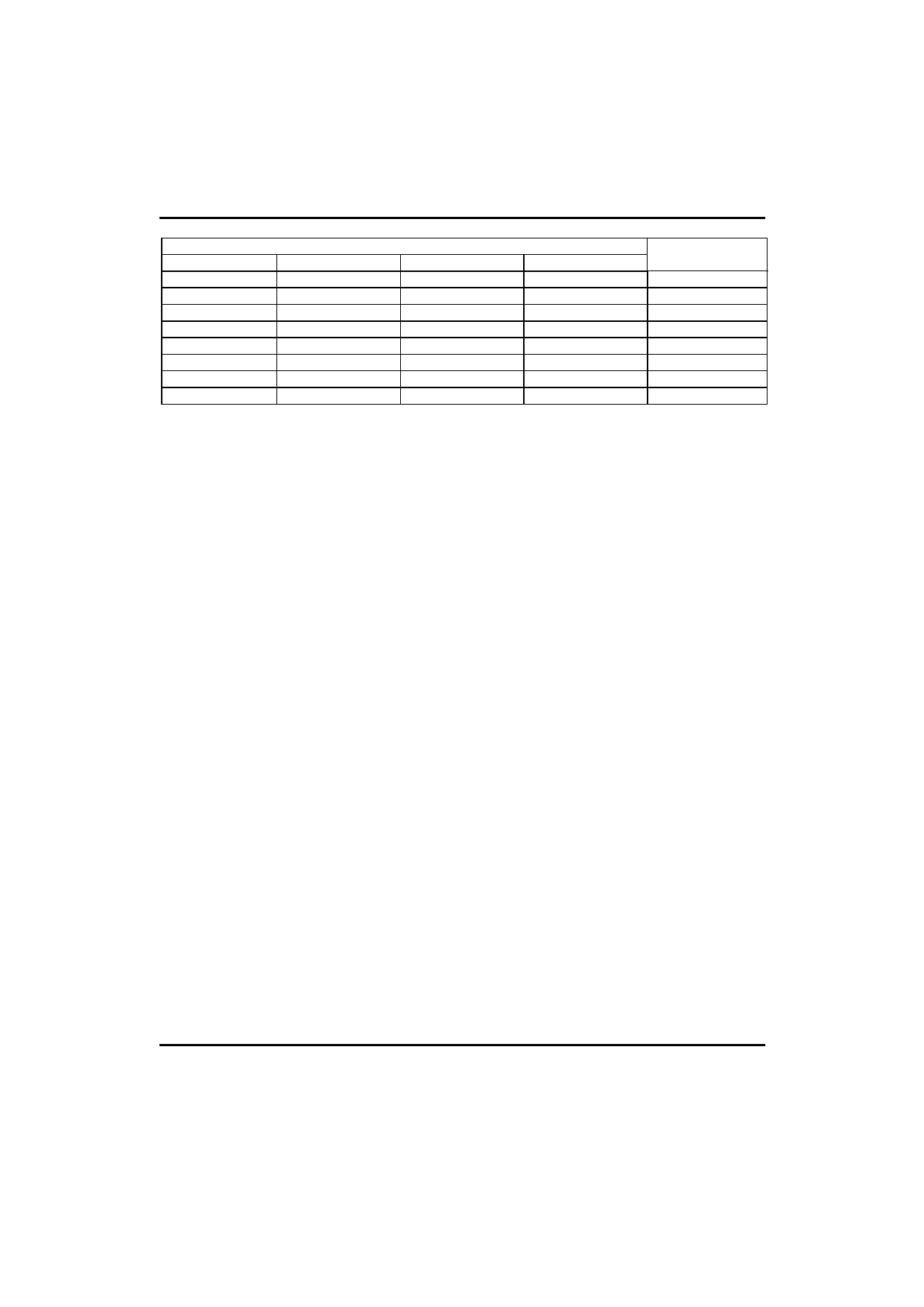
INPUTS
C1
C2
C3
Tx
Tx
1
Tx
Rx
Y
Rx
Tx
Y
Rx
Rx
X
Tx
Tx
0
Tx
Rx
0
Rx
Tx
0
Rx
Rx
X
OUTPUT MODE
C4
X
Transmit
Y
Fast Idle
Y
Fast Idle
1
Receive
X
Slow Idle
0
Slow Idle
0
Slow Idle
0
Slow Idle
A definition of the above terms:
1. “Transmit” means the transmit attenuator is fully on( +6dB). And the receive attenuator is at max. attenuation
( -46dB).
2. “Receive” means both attenuators are controlled by the volume control. At max. volume the receive attenuator is
fully on( +6dB), and the transmit attenuator is at max.attenuation( -46dB).
3. “Fast Idle” means both transmit and receive speech are present in approximately equal levels. The attenuators
are quickly switched(30 ms) to idle until one speech level dominates the other.
4. “Slow Idle” means speech has ceased in both transmit and receive paths. The attenuators are then slowly
switched(1 second) to the idle mode.
5. Switching to the full transmit or receive from any other mode is at the fast rate(~30 ms).
A summary of the truth table is as follows:
1. The circuit will switch to transmit if: (A) both transmit level detectors sense signals relative to the respective
receive level detectors( TLI1 versus RLI1, TLI2 versus RLI2) and (B) the transmit background noise monitor
indicates the presence of speech.
2. The circuit will switch to receive if: (A) both receive level detectors sense higher signal levels relative to the
respective transmit level detectors and (B) the receive background noise monitor indicates the presence of speech.
3. The circuit will switch to the fast Idle mode if the level detectors disagree on the relative strengths of the signal
levels, and at least one of the background noise monitor indicates speech. For example, referring to the Figure 2, if
there is sufficient signal at the microphone amp. Output(TLI2) to over-ride the speaker signal(RLI2), and there is
sufficient signal at the receive input(RLI1) to over-ride the signal at the hybrid output(TLI1), and either or both
background noise monitors indicates speech, then the circuit will be in the fast idle mode. Two conditions which
can cause the fast idle mode to occur are : (A) when both talkers are attempting to gain control of the system by
talking at the same time. And (B) when one talker is in a very noisy environment, forcing the other to continually
over-ride that noise level. In general, the fast idle mode will occur infrequently.
4. The circuit will switch to the slow idle mode when: (A) both talkers are quiet( no speech present) or (B) when one
talker’s speech level is continuously over-ride by noise at the other speaker’s location. The time required to switch
the circuit between transmit, receive, fast idle, and slow idle is determined in part by the components at the CT
pin( pin14), (see the section on switching timers for a more complete explanation of the switching time components
A schematic of the CT circuitry is shown in Figure 5, and operates as follows:
*RT is typically 120kΩ, and CT is typically 5µF.
*To switch to the receive mode, I1 is turned on( I2 is off), charging the external capacitor to +240mV above VB( An
internal clamp prevents further charging of the capacitor).
*To switch to the transmit mode, I2 is turned on( I1 is off), bringing down the voltage on the capacitor to -240mV
with respect VB.
*To switch to idle quickly(fast idle), the current sources are turned off, and the internal 2kΩ resistor is switched in,
discharging the capacitor to VB with a time constant= 2kΩ x CT.
*To switch to idle slowly(slow idle), the current sources are turned off, the switch at the 2kΩ resistor is open, and the
capacitor discharges to VB through the external resistor RT with a time constant=RT x CT.
UTC
UNISONIC TECHNOLOGIES CO., LTD. 10
QW-R108-007,A
Share Link: 