AS1320 查看數據表(PDF) - austriamicrosystems AG
零件编号
产品描述 (功能)
比赛名单
AS1320 Datasheet PDF : 12 Pages
| |||
AS1320
Data Sheet - Detailed Description
Low-Battery Cutoff
The AS1320 SHDNN trip threshold (1.228V) can be used as an input voltage detector that disables the device when
the battery input voltage falls to a pre-set level. An external resistor-divider network can be used to set the battery-
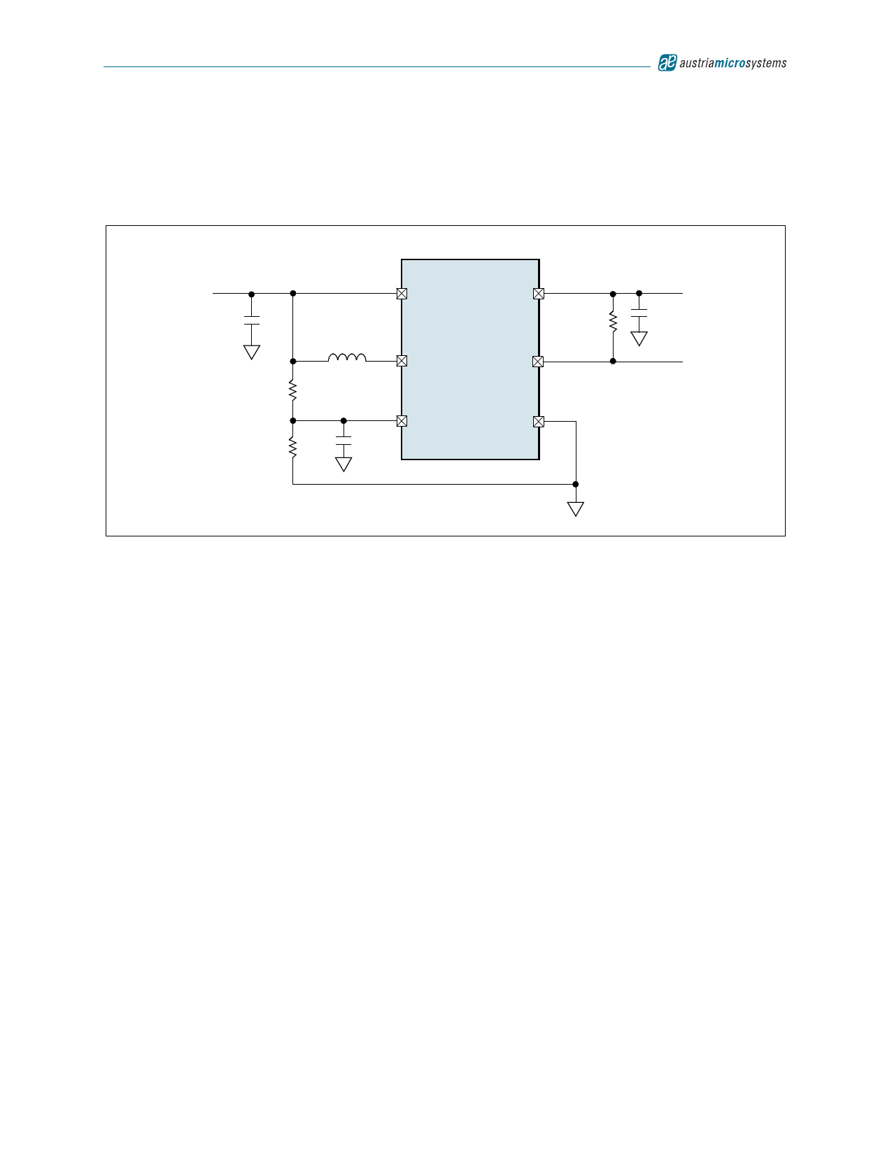
detection voltage (see Figure 16).
Figure 16. Low-Battery Cutoff Application Diagram
+1.5 to +3.5V
Battery
CIN
22µF
R1
220kΩ
R2
1MΩ
2
BATT
4
L1
LX
10µH
10nF
1
SHDNN
AS1320
5
OUT
R3
100kΩ
6
RESETN
3
GND
COUT
22µF
+3.3V
Output
Power-On
Reset
For the resistor-divider network shown in Figure 16, calculate the value for R1 by:
R1 = R2 x ((VOFF/VSHDNN) - 1)
Where:
VOFF is the battery voltage at which the AS1320 shuts down.
VSHDNN = 1.228V
The value of R2 should be between 100kΩ and 1MΩ to minimize battery drain.
(EQ 1)
Note: Input ripple can cause false shutdowns, therefore to minimize the effect of ripple, a low-value capacitor from
SHDNN to GND should be used to filter out input noise. The value of the capacitor should be such that the R/C
time constant is > 2ms.
Power-On Reset
The AS1320 provides a power-on reset output (RESETN) that goes high-impedance when the output reaches 90% of
its regulation point. RESETN goes low when the output is below 90% of the regulation point. A 100kΩ to 1MΩ pullup
resistor between pin RESETN and pin OUT can provide a microprocessor logic control signal.
Note: Connect pin RESETN to GND when the power-on reset feature is not used.
www.austriamicrosystems.com
Revision 1.03
8 - 12
Share Link: 