MD3221N 查看數據表(PDF) - Unspecified
零件编号
产品描述 (功能)
比赛名单
MD3221N Datasheet PDF : 26 Pages
| |||
↓Click!
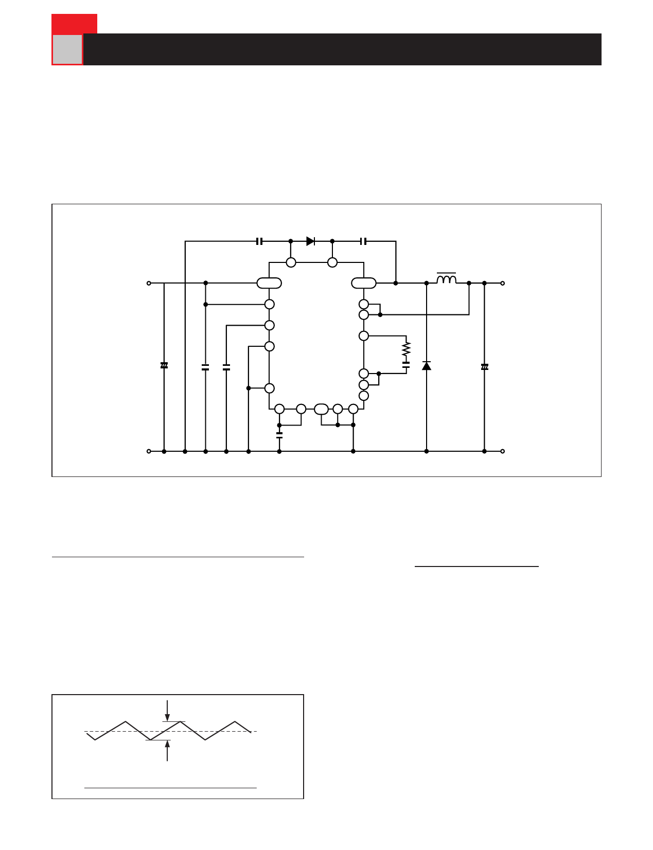
4 Selection of Primary Components and Pin Connections
The characteristics of the DC-DC converter are influenced by the IC itself, and also significantly by the
peripheral components of the circuit.
A well-designed circuit is necessary to make the most of the potential of the MD3221N. It is therefore necessary
to clarify the specifications of the required power supply, and to select components as follows.
● Standard Connection Diagram
+Vi
C1
+
G
C4
D1
C3
C7 C2
7
Vboot
18~21 VDD
24
VB
VOUT 11~14
6 VCC
32 S/S
1 R/C
MD3221N
OCL+ 25
OCL- 27
ampOUT 28
5 LC
Vref
2
amp- 29
ampIN 30
2.5V/3.3V 31
OSC GND P.GND1 P.GND2
3
4,26 8 16
C8
L1
+V0
R3
D2
C5
C6
+
G
◆Selecting the Output Choke Coil (inductor) (L1)
The choke coil has an important effect on power
supply performance. As a ripple current flows in the
inductor as shown in the diagram below, the
inductance should be selected to ensure that ΔI is
approximately 30% of the maximum output current
when the input voltage is at its maximum.
● Current Waveform in Output Choke Coil (L1)
ΔI
Io
0
L 1 =(V(i max)−VO)× VO [H]
ΔI ×V(i max)× f
V(i max):Maximum input voltage[V]
VO :Output voltage[V]
ΔI :30% of maximum output curren[t A]
f :Oscillation frequency (100kHz or 300kHz[) Hz]
I O :Maximum output curren[t A]
The inductor is generally selected on the basis
of the calculation, however in some cases the
nature of the product may require an inductor
which differs from the calculated value. An
inductor in which ΔI is between 20% and 40% of the
output current is recommended.
7
Share Link: 