AOZ1010 查看數據表(PDF) - Alpha and Omega Semiconductor
零件编号
产品描述 (功能)
比赛名单
AOZ1010 Datasheet PDF : 14 Pages
| |||
AOZ1010
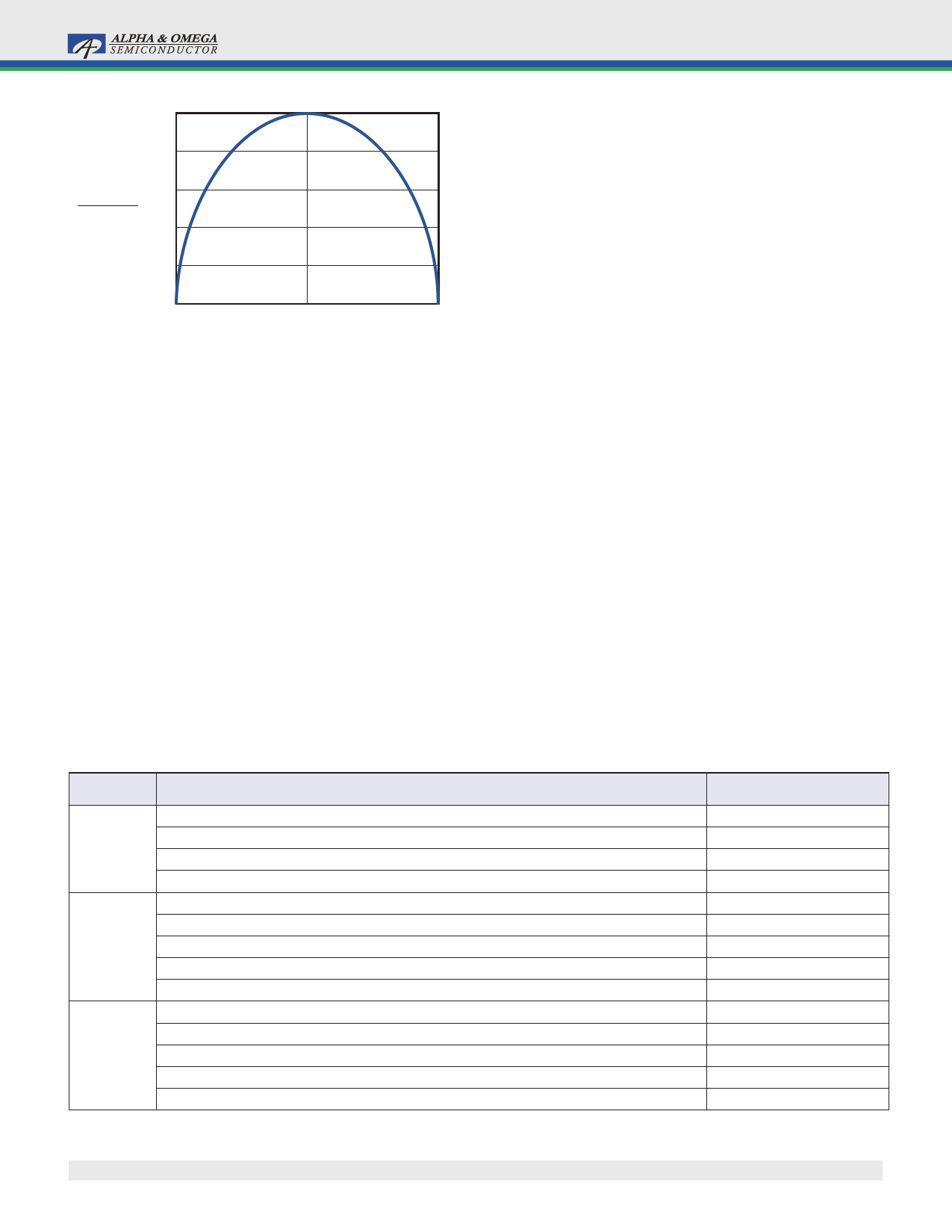
0.5
0.4
ICIN_RMS(m) 0.3
IO
0.2
0.1
0
0
0.5
1
m
Figure 2. ICIN vs. Voltage Conversion Ratio
For reliable operation and best performance, the input
capacitors must have current rating higher than ICIN_RMS
at the worst operating conditions. Ceramic capacitors are
preferred for input capacitors because of their low
ESR and high ripple current rating. Depending on the
application circuits, other low ESR tantalum capacitors
or aluminum electrolytic capacitors may also be used.
When selecting ceramic capacitors, X5R or X7R type
dielectric ceramic capacitors are preferred for their better
temperature and voltage characteristics. Note that the
ripple current rating from capacitor manufacturers is
based on certain amount of life time. Further de-rating
may be necessary for practical design requirement.
Inductor
The inductor is used to supply constant current to the
output when it is driven by a switching voltage. For a
given input and output voltage, inductance and switching
frequency together decide the inductor ripple current,
which is:
∆IL
=
--V-----O----
f ×L
×
1
–
-V-----O----
V IN
The peak inductor current is:
ILpeak
=
IO
+
∆-----I--L-
2
High inductance gives low inductor ripple current but
requires a larger size inductor to avoid saturation. Low
ripple current reduces inductor core losses. Low ripple
current also reduces RMS current through the inductor
and switches, which results in less conduction loss.
When selecting the inductor, make sure it is able to
handle the peak current at the highest operating temper-
ature without saturation.
The inductor takes the highest current in a buck circuit.
The conduction loss on the inductor needs to be checked
for thermal and efficiency requirements.
Surface mount inductors in different shape and styles are
available from Coilcraft, Elytone and Murata. Shielded
inductors are small and radiate less EMI noise, but they
cost more than unshielded inductors. The choice
depends on EMI requirement, price and size.
Table 2 lists some inductors for typical output voltage
design.
Table 2. Typical Inductors
VOUT
5.0V
3.3V
1.8V
L1
Unshielded, 4.7µH, LQH55DN4R7M03
Shielded, 4.7µH, LQH66SN4R7M03
Shielded, 5.8µH, ET553-5R8
Unshielded, 6.7µH, DO3316P-682MLD
Unshielded, 4.7µH, LQH55DN3R3M03
Shielded, 4.7µH, LQH66SN3R3M03
Shielded, 3.3µH, ET553-3R3
Unshielded, 4.7µH, DO3316P-472MLD
Unshielded, 4.7µH, DO1813P-472HC
Unshielded, 2.2µH, LQH55DN1R5M03
Shielded, 2.2µH, LQH66SN1R5M03
Shielded, 2.2µH, ET553-2R2
Unshielded, 2.2µH, DO3316P-222MLD
Unshielded, 2.2µH, DO1813P-222HC
Manufacture
MURATA
MURATA
ELYTONE
Coilcraft
MURATA
MURATA
ELYTONE
Coilcraft
Coilcraft
MURATA
MURATA
ELYTONE
Coilcraft
Coilcraft
Rev. 1.0 November 2006
www.aosmd.com
Page 8 of 14
Share Link: 