AD6426 查看數據表(PDF) - Analog Devices
零件编号
产品描述 (功能)
比赛名单
AD6426 Datasheet PDF : 50 Pages
| |||
Preliminary Technical Information
Keypad / Backlight / Display Interface
This interface combines all functions of display and keyboard
as shown in Table 10.
Table 10. Keypad / Backlight / Display Interface
Name
I/O Function
KEYPADROW5 : 0 I Keypad row inputs
KEYPADCOL3 : 0 O Keypad column strobes
BACKLIGHT
O Backlight control
DISPLAYCS
LCDCTL
GPIO3
GPIO4
O Display Controller chip
select
O LCD Control / Serial Display
Data Output
O Serial Display Data Output
O Serial Display Clock Output
By providing 4 keypad-column outputs (open drain, pull low)
and 6 keypad-row inputs the AD6426 can monitor up to 24
keys. Additionally, an extra column can be implemented by
using the “ghost column” method for a total of 30 keys. The
H8 processor is interrupted whenever a key is pressed. The
KEYPADCOL pins are connected to the Keypad Column3-0
flags in the KEYPAD COLUMN CC Control Register 9.
Bit KEYPAD COLUMN CC Control Register 9
3 : 0 Keypad Column 3-0
The six KEYPADROW pins are connected to the Keypad Row
5-0 flags in the KEYPADROW CC Control Register 10.
Bit KEYPADROW CC Control Register 10
5 : 0 Keypad Row 5-0
One backlight control output (BACKLIGHT) is provided,
which can be modulated to provide the same perceived
brightness for a reduced average current. Switching frequency
as well as duty cycle can be modified to compensate for
ambient lighting levels and changing battery voltage.
The BACKLIGHT output is activated by setting the
Backlight1 flag in the SYSTEM CC Control Register 0.
Bit SYSTEM CC Control Register 0
5 Backlight 1
Once activated, an internal PWM circuit can control the
frequency and the duty cycle of the output signal. The PWM
circuit is enabled by the Modulate1 flag in the BACKLIGHT
CC Control Register 50. To switch the backlight continuously
on, enable the Backlight 1 flag and disable the Modulate 1
flag.
AD6426
Bit BACKLIGHT CC Control Register 50
2 Modulate 1
1: 0 Backlight LED Control (1:0)
The frequency is determined by the flags Backlight LED
Control (1:0) in the same register as shown in Table 11.
Table 11. Backlight Frequency
Bit 1
0
0
1
1
Bit 0
0
1
0
1
Frequency
6.3475 kHz
12.695 kHz
25.390 kHz
50.780 kHz
Duty cycle can be selected between 0 and 124/128 in 32 steps
of 4/128 by programming the Backlight Duty Cycle (4:0) flags
in the POWER CONTROL INTERNAL CC Control Register
44.
Bit POWER CONTROL INTERNAL CC Control
Register 44
7 : 3 Backlight Duty Cycle (4:0)
The active period is determined according to the formula:
Active (high) Period =
Backlight Duty Cycle (4:0) × 4
128
The 6426 offers both parallel and serial interfaces for
connecting to LCD display controllers.
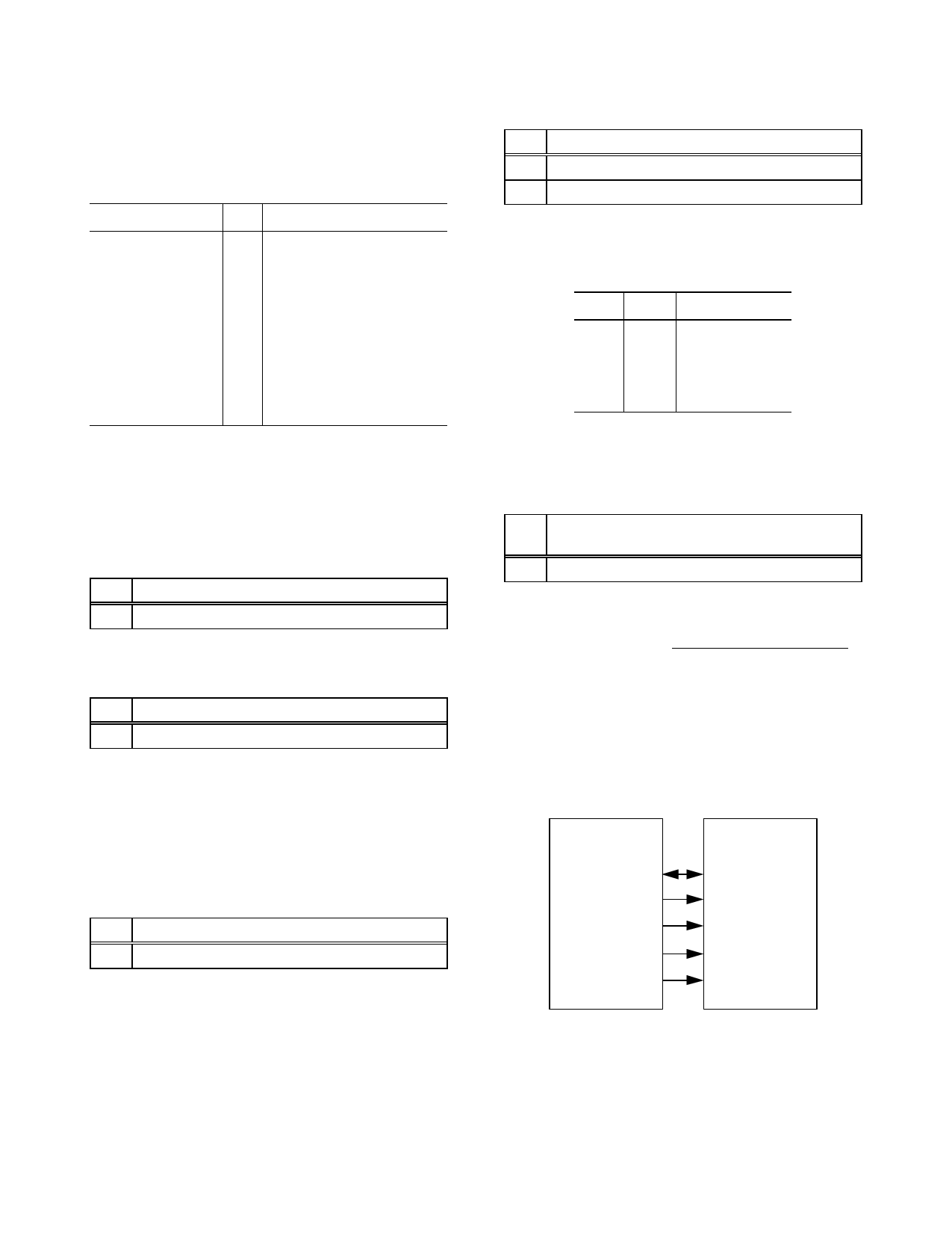
The parallel interface to a LCD controller is provided by two
dedicated control signals (LCDCTL and DISPLAYCS) and
parts of the address and data bus. A typical interface is shown
in Figure 5.
AD6426
DATA (15:8)
HWR
LCDCTL
ADD(0)
DISPLAYCS
LCD
Controller
DATA (7:0)
R/W
E
RS
CS
Figure 5. Parallel Display Interface
The on-chip control circuit automatically generates wait states
for interfacing to external display devices.
This Information applies to a product under development. Its characteristics and specifications are subject to change without notice. Analog Devices assumes no
obligation regarding future manufacture unless otherwise agreed to in writing. No responsibility is assumed by Analog Devices for its use; nor for any
infringements of patents or other rights of third parties which may result from its use. No license is granted by implication or otherwise under any patent or patent
rights of Analog Devices.
Revision Preliminary 2.3 (June 9, ´98)
- 19 -
Confidential Information
Share Link: 