P80C557E6 查看數據表(PDF) - Philips Electronics
零件编号
产品描述 (功能)
比赛名单
P80C557E6 Datasheet PDF : 64 Pages
| |||
Philips Semiconductors
Single-chip 8-bit microcontroller
Product specification
P83C557E6/P80C557E6
6.5 Pulse Width Modulated Outputs
The P8xC557E6 contains two pulse width modulated output
channels (see Figure 13). These channels generate pulses of
programmable length and interval. The repetition frequency is
defined by an 8-bit prescaler PWMP, which supplies the clock for the
counter. The prescaler and counter are common to both PWM
channels. The 8-bit counter counts module 255, i.e., from 0 to 254
inclusive. The value of the 8-bit counter is compared to the contents
of two registers: PWM0 and PWM1. Provided the contents of either
of these registers is greater than the counter value, the
corresponding PWM0 or PWM1 output is set LOW. If the contents of
these registers are equal to, or less than the counter value, the
output will be HIGH. The pulse-width-ratio is therefore defined by the
contents of the registers PWM0 and PWM1. The pulse-width-ratio is
in the range of 0/255 to 255/255 and may be programmed in
increments of 1/255.
Buffered PWM outputs may be used to drive DC motors. The
rotation speed of the motor would be proportional to the contents of
PWMn. The PWM outputs may also be configured as a dual DAC. In
this application, the PWM outputs must be integrated using
conventional operational amplifier circuitry. If the resulting output
voltages have to be accurate, external buffers with their own analog
supply should be used to buffer the PWM outputs before they are
integrated. The repetition frequency fpwm, at the PWMn outputs is
give by:
fPWM + 2
fCLK
(1 ) PWMP)
255
This gives a repetition frequency range of 123 Hz to 31.4 kHz
(fCLK = 16 MHz). By loading the PWM registers with either 00H or
FFH, the PWM channels will output a constant HIGH or LOW level,
respectively. Since the 8-bit counter counts modulo 255, it can never
actually reach the value of the PWM registers when they are loaded
with FFH.
When a compare register (PWM0 or PWM1) is loaded with a new
value, the associated output is updated immediately. It does not
have to wait until the end of the current counter period. Both PWMn
output pins are driven by push-pull drivers. These pins are not used
for any other purpose.
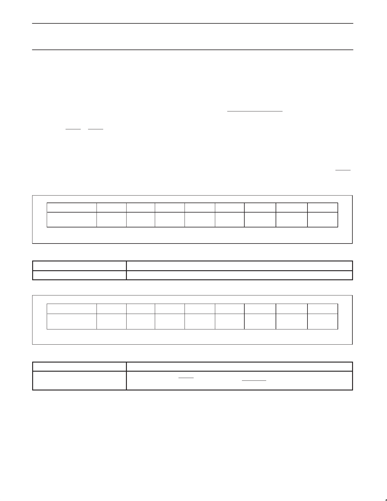
PWMP (FEH)
7
PWMP.7
6
PWMP.6
5
PWMP.5
4
PWMP.4
3
PWMP.3
2
PWMP.2
1
PWMP.1
0
PWMP.0
Figure 10. Prescaler frequency control register PWMP.
Table 6. Description of PWMP bits
BIT
FUNCTION
PWMP.0 to 7
Prescaler division factor = (PWMP) + 1
Reading PWMP gives the current reload value. The actual count of the prescaler cannot be read.
PWM0 (FCH)
7
PWM0.7
6
PWM0.6
5
PWM0.5
4
3
PWM0.4 PWM0.3
2
PWM0.2
1
PWM0.1
0
PWM0.0
Figure 11. Pulse width register PWM0.
Table 7. Description of PWM0 bits
BIT
PWM0.0 to 7
LOW/HIGH ration of PWM0 signal =
FUNCTION
(PWM0)
255 – (PWM0)
1999 Mar 02
16
Share Link: 