74ABT899 查看數據表(PDF) - Fairchild Semiconductor
零件编号
产品描述 (功能)
比赛名单
74ABT899 Datasheet PDF : 16 Pages
| |||
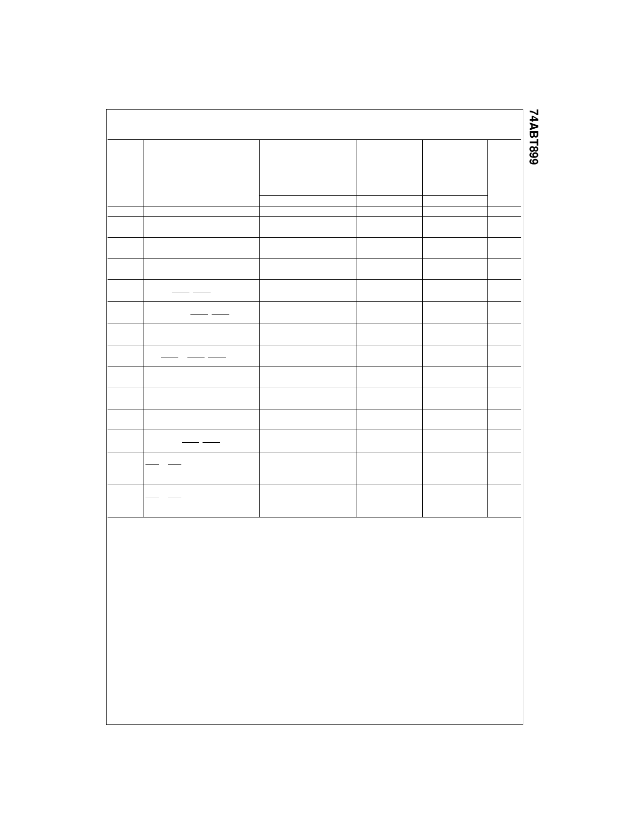
Extended AC Electrical Characteristics
(SOIC and PLCC Package)
TA = +25°C
TA = −40°C to +85°C TA = −40°C to +85°C
VCC = +5.0V
VCC = 4.5V–5.5V
VCC = 4.5V–5.5V
Symbol
Parameter
CL = 50 pF
9 Outputs Switching
CL = 250 pF
CL = 250 pF
1 Output Switching 9 Outputs Switching
Units
(Note 9)
(Note 10)
(Note 11)
Min
Typ
Max
Min
Max
Min
Max
fTOGGLE
tPLH
tPHL
tPLH
tPHL
tPLH
tPHL
tPLH
tPHL
tPLH
tPHL
Max Toggle Frequency
Propagation Delay
An to Bn
Propagation Delay
APAR to BPAR
Propagation Delay
An, Bn to BPAR, APAR
Propagation Delay
An, Bn to ERRA, ERRB
Propagation Delay
APAR, BPAR to ERRA, ERRB
100
MHz
1.5
6.2
2.0
7.2
2.5
9.5
ns
1.5
6.2
2.0
7.2
2.5
9.5
1.5
6.8
2.0
8.0
2.5
10.0
ns
1.5
6.8
2.0
8.0
2.0
10.0
2.5
10.0
3.0
12.5
3.5
13.5
ns
2.5
10.0
3.0
12.5
3.5
13.5
(Note 13)
3.0
12.0
(Note 13)
ns
3.0
12.0
(Note 13)
2.0
9.0
(Note 13)
ns
2.0
9.0
tPLH
Propagation Delay
tPHL
ODD/EVEN to APAR, BPAR
tPLH
Propagation Delay
tPHL
ODD/EVEN to ERRA, ERRB
(Note 13)
(Note 13)
2.5
9.9
(Note 13)
ns
2.5
9.9
2.0
8.8
(Note 13)
ns
2.0
8.8
tPLH
Propagation Delay
tPHL
SEL to APAR, BPAR
tPLH
Propagation Delay
tPHL
LEA, LEB to Bn, An
tPLH
Propagation Delay
tPHL
LEA, LEB to BPAR, APAR
tPLH
Propagation Delay
tPHL
LEA, LEB to ERRA, ERRB
(Note 13)
2.0
9.5
(Note 13)
ns
2.0
9.5
1.5
5.7
2.0
7.9
2.5
10.0
ns
1.5
5.7
2.0
7.9
2.5
10.0
1.5
9.5
2.0
12.0
2.5
13.0
ns
1.5
9.5
2.0
12.0
2.5
13.0
(Note 13)
2.0
11.5
(Note 13)
ns
2.0
11.5
tPZH
Output enable time
1.5
7.0
2.0
8.5
2.5
10.5
tPZL
GBA or GAB to An,
1.5
7.0
2.0
8.5
2.5
10.5
ns
APAR or Bn, BPAR
tPHZ
Output disable time
1.0
6.5
tPLZ
GBA or GAB to An,
1.0
6.5
(Note 12)
(Note 12)
ns
APAR or Bn, BPAR
Note 9: This specification is guaranteed but not tested. The limits apply to propagation delays for all paths described switching in phase (i.e., all LOW-to-
HIGH, HIGH-to-LOW, etc.).
Note 10: This specification is guaranteed but not tested. The limits represent propagation delay with 250 pF load capacitors in place of the 50 pF load capac-
itors in the standard AC load. This specification pertains to single output switching only.
Note 11: This specification is guaranteed but not tested. The limits represent propagation delays for all paths described switching in phase (i.e., all LOW-to-
HIGH, HIGH-to-LOW, etc.) with 250 pF load capacitors in place of the 50 pF load capacitors in the standard AC load
Note 12: The 3-STATE delay time is dominated by the RC network (500Ω, 250 pF) on the output and has been excluded from the datasheet.
Note 13: Not applicable for multiple output switching.
7
www.fairchildsemi.com
Share Link: 