PDI1394P25BY 查看數據表(PDF) - Philips Electronics
零件编号
产品描述 (功能)
比赛名单
PDI1394P25BY Datasheet PDF : 42 Pages
| |||
Philips Semiconductors
1-port 400 Mbps physical layer interface
Product data
PDI1394P25BY
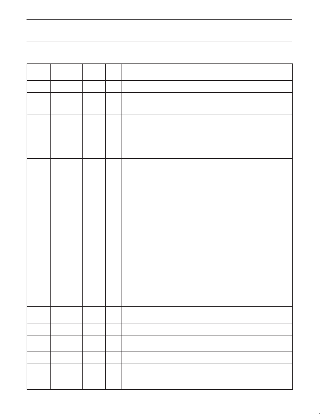
5.0 PIN DESCRIPTION
Name
Pin Type
LQFP
Pin
Numbers
AGND
Supply
26, 32,
36
AVDD
Supply
25, 35
BRIDGE
CMOS
23
C/LKON CMOS 5 V tol 15
CPS
CMOS
20
CTL0,
CTL1
D0–D7
DGND
DVDD
CMOS 5 V tol 2, 3
CMOS 5 V tol
Supply
Supply
4, 5, 6, 7,
8, 9, 10,
11
14, 46,
47
21, 44,
45
I/O
Description
— Analog circuit ground terminals. These terminals should be tied together to the low
impedance circuit board ground plane.
— Analog circuit power terminals. A combination of high frequency decoupling capacitors on
each side are suggested, such as paralleled 0.1 µF and 0.001 µF. These supply terminals
are separated from PLLVDD and DVDD internal to the device to provide noise isolation.
They should be tied at a low impedance point on the circuit board.
I BRIDGE input. This input is used to set the Bridge_Aware bits located in the
Vendor-Dependent register Page 7, base address 1001b, bit positions 6 and 7. This pin is
sampled during a hardware reset (RESET low). When the BRIDGE pin is tied low (or
through a 1 kΩ resistor to accommodate other vendor’s pin-compatible chips), the
Bridge_Aware bits are set to “00” indicating a “non-bridge device.” When the BRIDGE pin
is tied high, the Bridge_Aware bits are set to “11” indicating a “1394.1 bridge compliant”
device. The default setting of the Bridge_Aware bits can be overridden by writing to the
register. The Bridge_Aware bits are reported in the self-ID packet at bit positions 18 and
19.
I/O Bus Manager Contender programming input and link-on output. On hardware reset, this
terminal is used to set the default value of the contender status indicated during self-ID.
Programming is done by tying the terminal through a 10-kΩ resistor to a high (contender)
or low (not contender). The resistor allows the link-on output to override the input.
If this pin is connected to a LLC driver pin for setting Bus Manager/IRM contender status,
then a 10-kΩ series resistor should be placed on this line between the PHY and the LLC
to prevent possible contention. In this case. the pull-high or pull-low resistors mentioned in
the previous paragraph should not be used. Refer to Figure 9.
Following hardware reset, this terminal is the link-on output, which is used to notify the
LLC to power-up and become active. The link-on output is a square-wave signal with a
period of approximately 163 ns (8 SYSCLK cycles) when active. The link-on output is
otherwise driven low, except during hardware reset when it is high impedance.
The link-on output is activated if the LLC is inactive (LPS inactive or the LCtrl bit cleared)
and when:
a) the PHY receives a link-on PHY packet addressed to this node,
b) the PEI (port-event interrupt) register bit is 1, or
c) any of the CTOI (configuration-timeout interrupt), CPSI (cable-power-status interrupt),
or STOI (state-timeout interrupt) register bits are 1 and the RPIE (resuming-port
interrupt enable) register bit is also 1.
Once activated, the link-on output will continue active until the LLC becomes active (both
LPS active and the LCtrl bit set). The PHY also de-asserts the link-on output when a
bus-reset occurs unless the link-on output would otherwise be active because one of the
interrupt bits is set (i.e., the link-on output is active due solely to the reception of a link-on
PHY packet).
NOTE: If an interrupt condition exists which would otherwise cause the link-on output to
be activated if the LLC were inactive, the link-on output will be activated when the LLC
subsequently becomes inactive.
I Cable Power Status input. This terminal is normally connected to cable power through a
390 kΩ resistor. This circuit drives an internal comparator that is used to detect the
presence of cable power.
I/O Control I/Os. These bi-directional signals control communication between the PDI1394P25
and the LLC. Bus holders are built into these terminals.
I/O Data I/Os. These are bi-directional data signals between the PDI1394P25 and the LLC.
Bus holders are built into these terminals. Unused Dn pins should be pulled to ground
through 10 kΩ resistors.
— Digital circuit ground terminals. These terminals should be tied together to the low
impedance circuit board ground plane.
— Digital circuit power terminals. A combination of high frequency decoupling capacitors
near each side of the IC package are suggested, such as paralleled 0.1 µF and 0.001 µF.
Lower frequency 10 µF filtering capacitors are also recommended. These supply terminals
are separated from PLLVDD and AVDD internal to the device to provide noise isolation.
They should be tied at a low impedance point on the circuit board.
2002 Oct 11
4
Share Link: 