UPC1935 查看數據表(PDF) - NEC => Renesas Technology
零件编号
产品描述 (功能)
比赛名单
UPC1935 Datasheet PDF : 28 Pages
| |||
µ PC1935
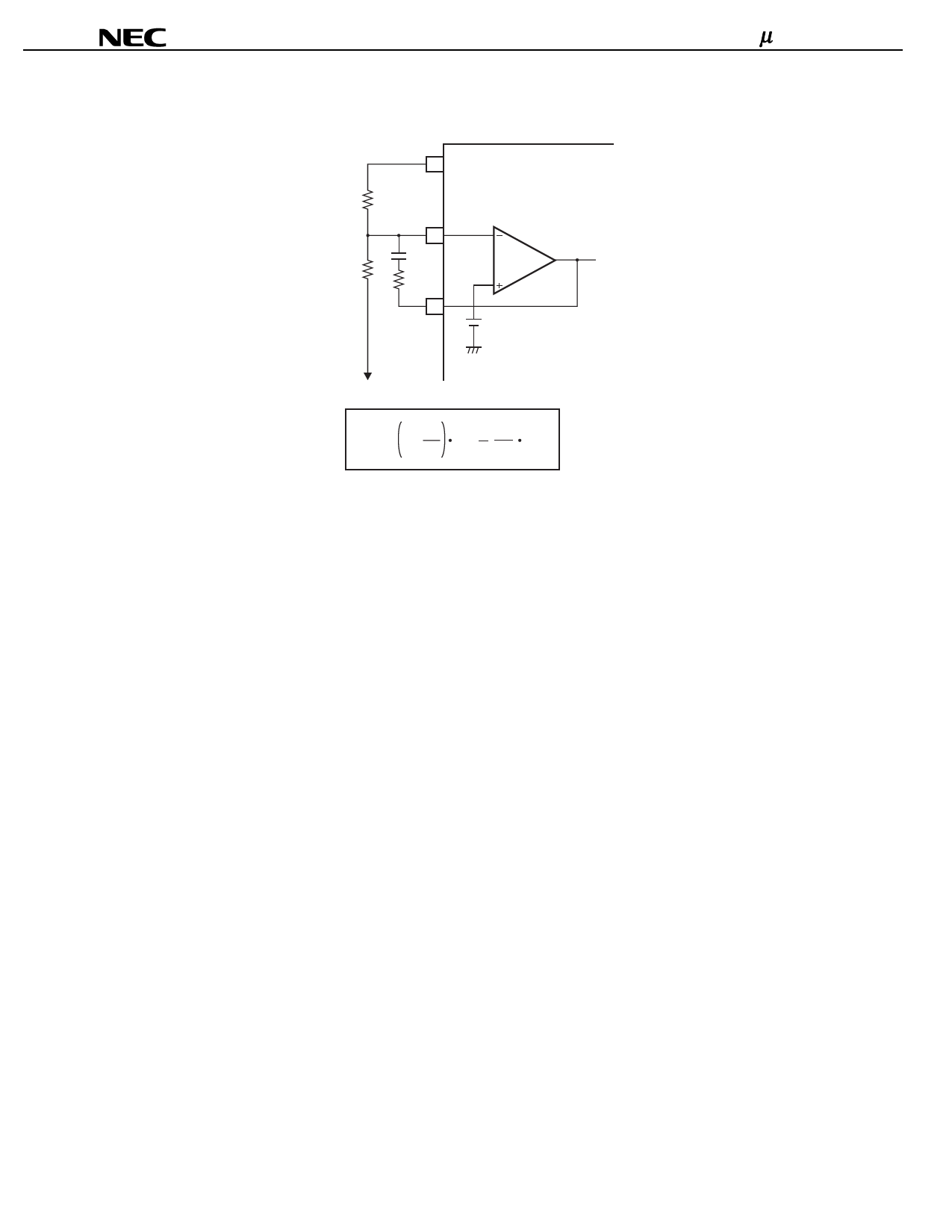
(3) When setting a negative output voltage using error amplifier E/A3.
2 VREF
R1
15
CNF
R2
RNF
E/A3
14
0.3 V
VOUT (negative voltage)
VOUT = 1 + R2
R1
0.3
R2 VREF
R1
3.2 Setting the Oscillation Frequency
Choose RT according to the oscillation frequency (fOSC) vs timing resistor (RT) characteristics (refer to Typical
Characteristics Curves fOSC vs RT). The formula below (3-1) gives an approximation of fOSC. However, the result of
formula 3-1 is only an approximation, and the value must be confirmed in actual operation, especially for high-frequency
operation.
fOSC[Hz] ≅ 1.856 x 10⁹/RT[Ω]
(3-1)
3.3 Preventing Malfunction of the Timer Latch-Method Short Circuit Protection Circuit
The timer latch short-circuit protection circuit operates when the error amplifier outputs of channel 1 or channel 2 (pin 7
and 10) exceed approximately 1.9 V, or when the error amplifier output of channel 3 (pin 14) goes below approximately
0.63 V, and cuts off the output. However, if the rise of the power supply voltage is fast, or if there is noise on the DLY pin
(pin 5), the latch circuit may malfunction and cut the output off.
To prevent this, keep the wiring impedance between the DLY pin and the GND pin (pin 4) low, and avoid applying noise
to the DLY pin.
Data Sheet G13418EJ3V0DS00
15
Share Link: 