PBL3852 查看數據表(PDF) - Ericsson
零件编号
产品描述 (功能)
比赛名单
PBL3852 Datasheet PDF : 24 Pages
| |||
PBL 3852
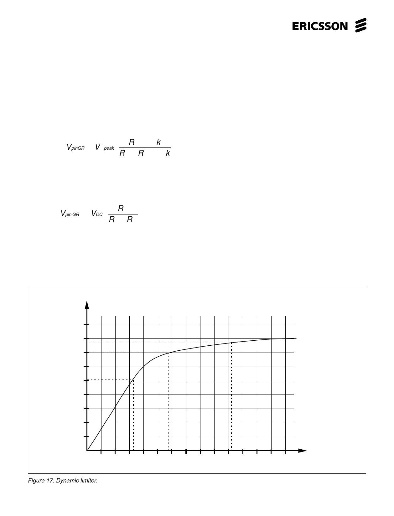
Dynamic limiter
The dynamic limiter consists of a full wave rectifier that senses the signal amplitude on the line and produces a control signal that
reduces the gain of the transmitter and the receiver when the signal on the line reaches a certain set level. The reason to this is to
reduce distortion at high signal levels (See fig. 15, 16, 17, 18 and 34).
The attac point for the dynamic limiter is set by the voltage divider R8, R10 and the internal resistor of 30k (peak signal) the lower
frequency limit is set by the input capacitor C5 to pin 7 (RTC). The diodes Da and Db that make the function logarihtmic have a 0.6V
voltage drop on this signal which is then added to the reference ≈0.855V. The signal will be further rectified with a ratio 1:1, attenuated
(can be neglected) in the filter at pin GR and forvarded to the gain regulation.
At a enough high signal in, the voltage at pin GR is set by:
VpinGR ≈ V 2peak ⋅ R 8 / / 30k
− 0.6 + 0.855
R 10 + R 8 / / 30k
The time constant ”up” is set by the internal ≈ 2.2k and C7, where the time constant ”down” is R14 parallel with R15 and C7. The
DC-voltage at pin GR with no input signal is set by the resistor divider R14 and R15 at a level just below where regulation starts see
fig. 16. It is possible by adjusting this DC-level down to make the time constant ”up” longer. With no AC signal in, or a very small and
no resistors R14,R15 the rectifier output is at reference in level (0.855V). At no AC signal in the voltage at pin GR is set up by:
Vpin GR = VDC1 ⋅
R15
R14 + R15
If gain regulation with line length is used together with softclipping the time constant ”down” will be influenced by the parallel value of
R14,R15, and R16. The DC-level at pin GR without AC signal will be set by these three resistors.
V2
Vp
2.25
2
1.75
1.5
1.25
1
0.75
0.5
0.25
V3
1 2 3 4 5 6 7 8 9 10 11 12 13 14 mVp
Vin +10dB
+15dB
+20dB
Figure 17. Dynamic limiter.
12
Share Link: 