PBL3852 查看數據表(PDF) - Ericsson
零件编号
产品描述 (功能)
比赛名单
PBL3852 Datasheet PDF : 24 Pages
| |||
PBL 3852
line resistance RLine and the line feeding
data of the exchange. A decoupling
capacitor is needed between pins +C and
-L. The V+C supply changes its voltage
linearly with the line current. It can be
used to feed an electret microphone.
Caution must be taken though not to drain
too much current out of this output
because it will affect the internal quick
start circuit by locking itself into active
state. (max. permissible current drain
600µA)
Care has to be taken when desiding the
resistance value of R19. All resistances
that are applied from +Line to ground
(-Line) will be in parallel, forming the real
impedance towards the line. This will
sometimes result in, that the ohmic value
of R19 is increased in order to comply to
the impedance specification towards the
line. The speech circuit sinks ≈ 1mA into
the pin 4, which means that the working
voltage for the speech function +V will
decrease with the increasing R19, thus
starving in the end the circuit of its
working voltage. This dependency is often
falsely taken as a sign of that the circuit
does not work down to the low line current
specified, but in fact it is the working
voltage at pin 4 that has became too low.
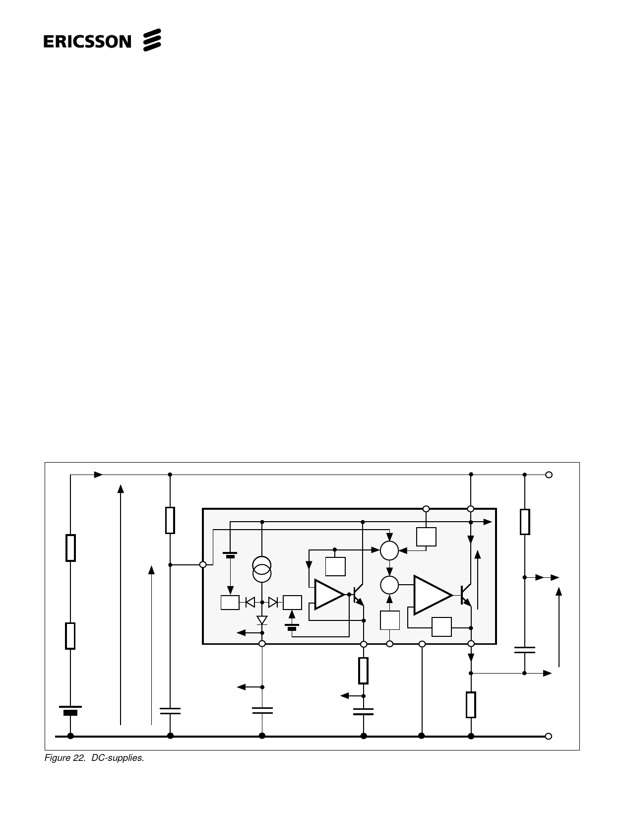
It is obvious that this problem is also
connected into what kind of DC-
characteristic is set (see fig. 22).
The circuit has further two temperature
and line current compensated DC
supplies DC1 and DC2. DC1 is a high
precision voltage supply for supplying
microphones, opto couplers etc. it is also
suitable as a voltage reference. Typical
voltage 2.1V down to line voltage of 4.1V,
in case the line voltage is lower than 4.1V
calculate; actual line voltage minus 1.9V.
In order to prevent noise entering the
line, a resistor is recommended in series
with this output.
DC2 is a voltage clamped current
source that is suitable to be used in
supplying diallers and micro processors
but also parts of circuitry that need supply
in hook on condition. The typical voltage
is 3.7V down to line voltage of 4.75V If the
line voltage is lower than 4.75V calculate;
actual line voltage minus 1.25V. The
current supply to a memory retention
capacitor is easiest isolated with a diode,
the capacitor preferably a low voltage
drop type, and in hook on condition it has
to have charge path from an uninterrupted
point on the + line. If a diode is not used
for isolation care must be taken that no
current can be taken out of the reservoir
capacitor at or after ”hook-on”. It must be
secured that the receiver can not get any
input signal and that there is a capacitor
in series with the output to isolate a DC
load. It is possible to feed an external
shunt regulator directly from the DC2
output for lower voltage than the clamp
level. The line voltage can for a short
period of time go below the voltage at
this output without affecting the line
characteristics, this because the circuit
tries to keep the current taken from the
line constant at all times. The receiver
has its current supply (pt. a in fig. 22)
from the DC2 supply. A series resistor at
the output will limit the peak current
which is one way to limit the possibility
for an acoustic shock at the earphone.
The handsfree circuits ( PBL 3786,
3786/2 and 3880) speech switching
function can be supplied directly from this
output.
The fourth DC-supply VPh has an
advantage that it does not influence the
circuits DC characteristics even at high
current drain. The supply has a floating
ground reference and is used to supply
the power amplifier of a handsfree
telephone. (PBL 3786, 3786/2 and 3880)
These circuits have a current controlled
charging of the supply capacitor and the
control signal is taken across the
resistorR7.
In case a monitor amplifier is required
where the ground reference is hardly
necessary, it can be supplied from VPh .
IL
RL
R feed
+
VE
VL R19
V+C
PBL 3852
+
+C
V
4
I
Ref
+
+
Clamp
Clamp
-
+
a
8
Lim
9
3
DC2
DC2
+
C9
+
C3
DC1
TI
R3
DC1
+
C2
DCC
5
I/U
+L
1
IT
VT
+
T
-
ƒ
14
2
-L
TO IS
R7
Figure 22. DC-supplies.
+Line
R Ph
IPh
VPh
+
CPh
-Line
15
Share Link: 