PBL3852 查看數據表(PDF) - Ericsson
零件编号
产品描述 (功能)
比赛名单
PBL3852 Datasheet PDF : 24 Pages
| |||
PBL 3852
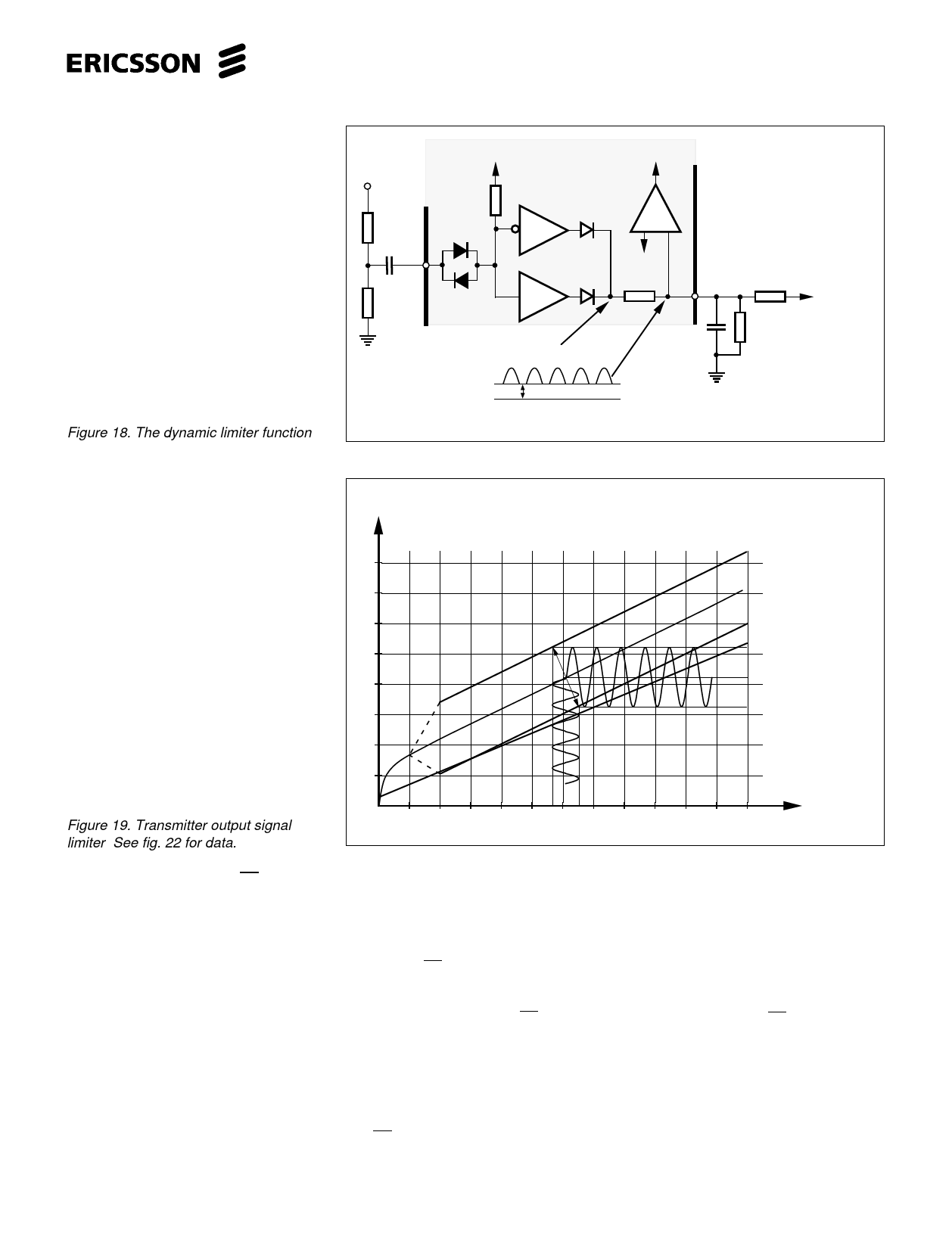
Figure 18. The dynamic limiter function
Int. ref.0.855V
Line
30k
R10
Da
C5
7
RTC
R8
Db
Rectifier output
To gain regulation
Ref.
(1.16V)
10 GR
2.2k
+
C7
R14
R15
In ref.=0.855V
0V
Signal at GR without C7
DC 1
Figure 19. Transmitter output signal
limiter. See fig. 22 for data.
V
Amplitude limiter
16
VL
14
12
Amplitude limiter
10
ISR7
+
VTsat
(1x
1x
diode
Vce)
8
VTline 4Vp-p
6
4
2
IL
20
40
60
80
100
120
mA
Power down and input PD
During pulse dialling or register recall
(time controlled line break) the telephone
line is interrupted, hence the transmis-
sion and peripheral circuits are not
supplied during the breaks from the
line.The circuit has therefore an internal
power-down function that automatically
shuts down the current consuming parts
when the line voltage drops under a
certain level. This function reduces the
internal current consumption I+C
to≈120µA that in its turn minimizes the
charge up time of the capacitor C9 when
the line feed returns. The timing and pulse
shape at LD - dialling is improved. In
some cases the parameters around LD -
dialling can be improved by switching the
voltage at this input. Most of the modern
processors used for LD-dialling do also
supply a ”window” signal for the duration
of the LD-digit stream. This signal can be
used for the PD input. An improvement of
receiver and transmitter output swing at
very low line currents (IL<10mA) can be
achieved by controlling this PD input with
two resistors and a diode, maybe a
capacitor C1 is necessary, see fig. 21.
The circuit can be made to work down at
1.8V line voltage and 2.8mA line current.
Great care has to be taken to secure
against a possible latchup.
The PD input should not be held ”down”
at hook-on or at start to hook-off this
restricting the internal reference voltage
buid up and the circuit to ”wake up”. (It is
good practice to isolate the input with a
diode according to fig. 21, an open
collector drain can also be used). If the
adjusting feature with the two resistors is
used, it does not endanger the ”waking
up” process because the line voltage via
R19 will lift the level at PD input over the
critical reference voltage level of 1.16V. In
case this input is not used it should be left
”open”.
13
Share Link: 