PBL3852 查看數據表(PDF) - Ericsson
零件编号
产品描述 (功能)
比赛名单
PBL3852 Datasheet PDF : 24 Pages
| |||

PBL 3852
PBL 3852
Rx
8
14
DC2
-L
+
C3
HANDSFREE
PBL 3786
PBL 3786/2
PBL 3880
PBL 3881
V+
GND
+
DIALLER
MEMORY
V+
GND
V+
GND
D2
Current
(Shottky) +
thief
Uninterrupted
+ Line
Large electrolytic
or "Gold cap".
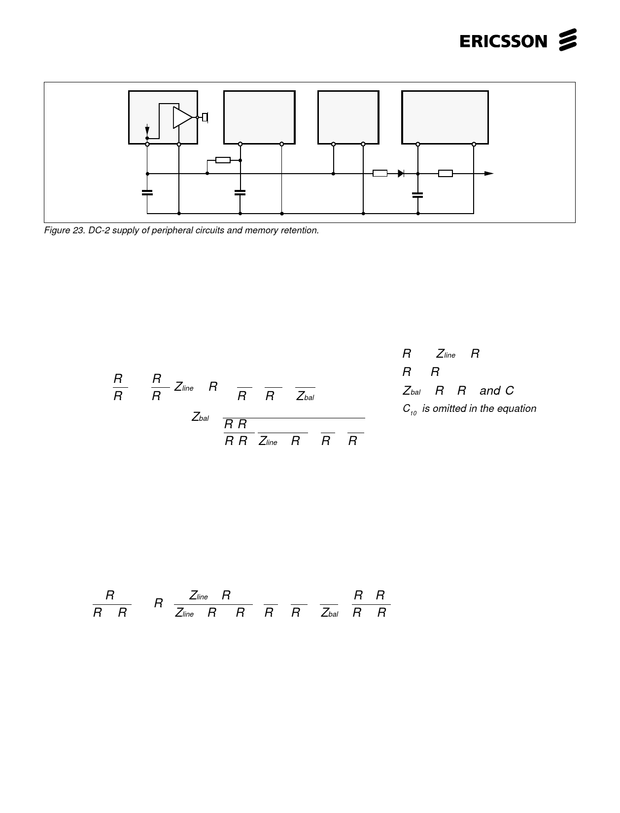
Figure 23. DC-2 supply of peripheral circuits and memory retention.
Side tone suppression (see fig. 24, 26)
The side tone suppression is achieved by adding two signals V+L and VTO in opposite phase at input RI. Because of the complex
line impedance Zline, VTO must be compensated by Zbal in order to get the correct level and phase for the signal to be summed.
Maximum compensation is achieved when following conditions are fulfilled:
drops below 2V or the line voltage below
R7
R9
=
R 11
R 18
Zline
/
/R 19
1
R9
+
1
R 11
+
1
Zbal
This gives Zbal to be:
Zbal = R7R18
1
1 −1− 1
R9R11 Zline / /R19 R9 R11
R 18 〉〉 Zline / /R 19
R9〉〉 R7
Zbal = R 12,R 13 and C 6
C10 is omitted in the equation
Following should be noted at designing the side tone network:
The impedance of the side tone network in parallel with the R7 should not be too low. This does influence the transmitter gain
and frequency response. (Zbal + Rg >> R7)
R11 should not be low compared with Zbal this will influence the receiver frequency response. (R11 >> Zbal)
The side tone network impedance, parallel with the receiver input impedance Zin, should not be too high compared with Zin this
influencing the spread in the receiver gain. ( Zin >> side tone network impedance, R18//R17// (R11+R9//Zbal ))
Maximum compensation without any assumption is obtained when following condition is fulfilled:
R7
R7 + R9
=
R11
Zline / /R19
Zline / /R19 + R18
1
R9
+
1
R11
+
1
Zbal
−
R7
R7
/ R9
+ R9
In practice Zline varies with the line type, length and the feeding system parameters. Therefore Zbal should be chosen to give a
satisfactory side tone suppression at an average line length.
An other method is to make R18 complex. See fig.25. This will be advantageous in case the R7 is low ohmic (10-39Ω) because
this coupling will give +6 dB more signal for the side tone balancing. Warning! At low values of R7 the circuit will have an insuffi-
cient overcurrent protection. A over voltage protection with lower limiting level has to be used across the circuit. It also will make
it possible to implement a better working volume control for the earphone. There will be some disadvantages as: More difficult to
trim and it needs closer tolerance components.
16