PBL3852 查看數據表(PDF) - Ericsson
零件编号
产品描述 (功能)
比赛名单
PBL3852 Datasheet PDF : 24 Pages
| |||
PBL 3852
Short about Radio Frequency
Interference RFI.
HF suppression at the microphone
input
The HF-signal at the microphone input
can be seen composed as of two
components. One component being the
differential (between pins 12and 13) and
the second related to ground at pin 14. Of
these two, the first is the most serious,
entering the amplifier directly being
amplified and detected. The second
component is less serious because it
affecting both inputs alike and most of it
will be balanced out of the amplifier.
There might be the case where the HF-
signal will have such an amplitude that
the amplifier can not balance it out. Then
components must be filtered with
capacitors and maybe resistors. It is
extremely important that everything that is
done at the input is in balance, otherways
the problem might get worse instead of
better. The extreme balance requirement
goes all the way to the PCB-layout. Small
unbalance signals can be corrected with
capacitors marked with *) this requiring
high precision components. See fig 28.
The solution shown is rather expensive
but with precision components it renders
good filtering at the input. If the main
problem is the signal between the inputs,
try to increase the 1nF capacitor but
make the others procentually smaller in
order to maintain the frequency re-
sponse. A more simple solution, that is
sufficient in most of the cases is also
shown in fig. 27.
10n 10n
100Ω
Mic.
100Ω
*
1n
*
10n
10n
11
13
M
12 +
PBL3852
14
Line
<20n
Mic.
1n
<20n
11
13
M
12 +
PBL3852
14
Line
Dynamic microphone
Dynamic microphone (simplified)
Figure 27. RFI elimination at microphone amplifier input .
+
11-15k
10n
11
200-
470Ω
+
13
1n
1µ
Mic.
M
+ 12 +
10n
200-
470Ω
1µ
PBL3852
14
Line
Electret microphone
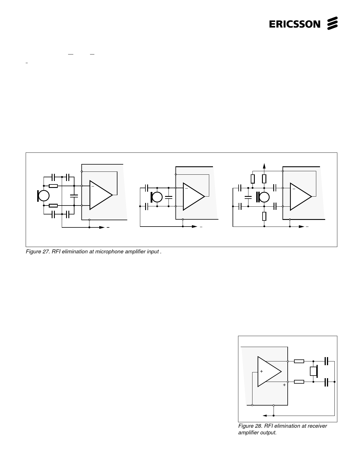
HF-suppression at the receiver output
The problem here is of the same kind as
at the microphone amplifier input but will
be easier to solve because of the much
lower impedance and level of gain. The
solution is shown in the fig. 28. No
capacitors should be connected directly
from pins17 or 18 to ground because of
the low outputimpedance, series
resistance of at least 10Ω must be used if
there is a tendency to self oscillation.
Other paths for the HF-signal to enter
the audible system
To find out if the problem originates in the
DTMF-generator disconnect the generator
and short the mute input to -line, pin 14. If
the problem is small try to connect a
capacitor from mute input to -line pin 14.
Modern CMOS circuits are more sensitive
to RFI because of their high impedance at
the input pins, especially the keyboard
inputs to the DTMF-generator. These
inputs are not possible to filter with large
capacitors because of the keyboard
scanning pulses (1µs) that will be loaded
down. To shield the keyboard will some
times help. The polarity guard bridge can
also act as a rectifier and demodulator, of
the HF-signals. Connect 1nF capacitors
across each diode in the bridge. There is
a capacitor across the line C10, this is for
RFI suppression but also to stabilise the
whole system.
The cappacitor C10 shoud be connected
like in figure 30. The frequencies at which
the RFI comes through are in the region
of 10-1000MHz. The resistance of the
C10 will be somewhere 0.01-10Ω hence
even the shortest lenght of connector on
the PCB board or wire wil be in the same
region of resistance and thus of greatest
of importance. These actions described
above should, when applied correctly,
take care of the RFI coming in from the
telephone line. The second way for the
RFI to enter the system is to penetrate the
PCB board capacitively. The test methode
is to place a metal sheet under the
telephone set to be tested and inject the
sheet with RF signal. The most
used and effective counter measure to
this kind of RFI penetration is to shield
the telephone set, at least the bottom
of it, that is closest to the main PCB
board by metal foil or by spraying the
plastic casing with metallic matter. See
figure 29. This methode does not
necessarily count out the RFI
components that are recommended
earlier.
17 10-100Ω
-
<47n
Rx
16
10-100Ω
<47n
PBL3852
15
14
- Line
Figure 28. RFI elimination at receiver
amplifier output.
18
Share Link: 