CDB6403 查看數據表(PDF) - Cirrus Logic
零件编号
产品描述 (功能)
比赛名单
CDB6403 Datasheet PDF : 54 Pages
| |||
CS6403
Mode 1:
Application:
1.1:
1.2:
Configuration
Master Interface (e.g. CODEC⇔CS6403)
Low-cost speaker phone
Short-Frame Mode
Long-Frame Mode
0
1
0
1
1
0
Mode 2:
Application:
2.1:
2.2:
Slave Interface (e.g. DSP⇔CS6403)
Digital cellular
16-bit Mode
8-bit Mode
0
0
1
0
0
0
Table 2. CS6403 Configurations
Mode Selection
The behavior of the CS6403 is controlled by
configuration-control input pins. The behavior of
the CS6403 for each possible state of these con-
trol signals is illustrated in Table 2.
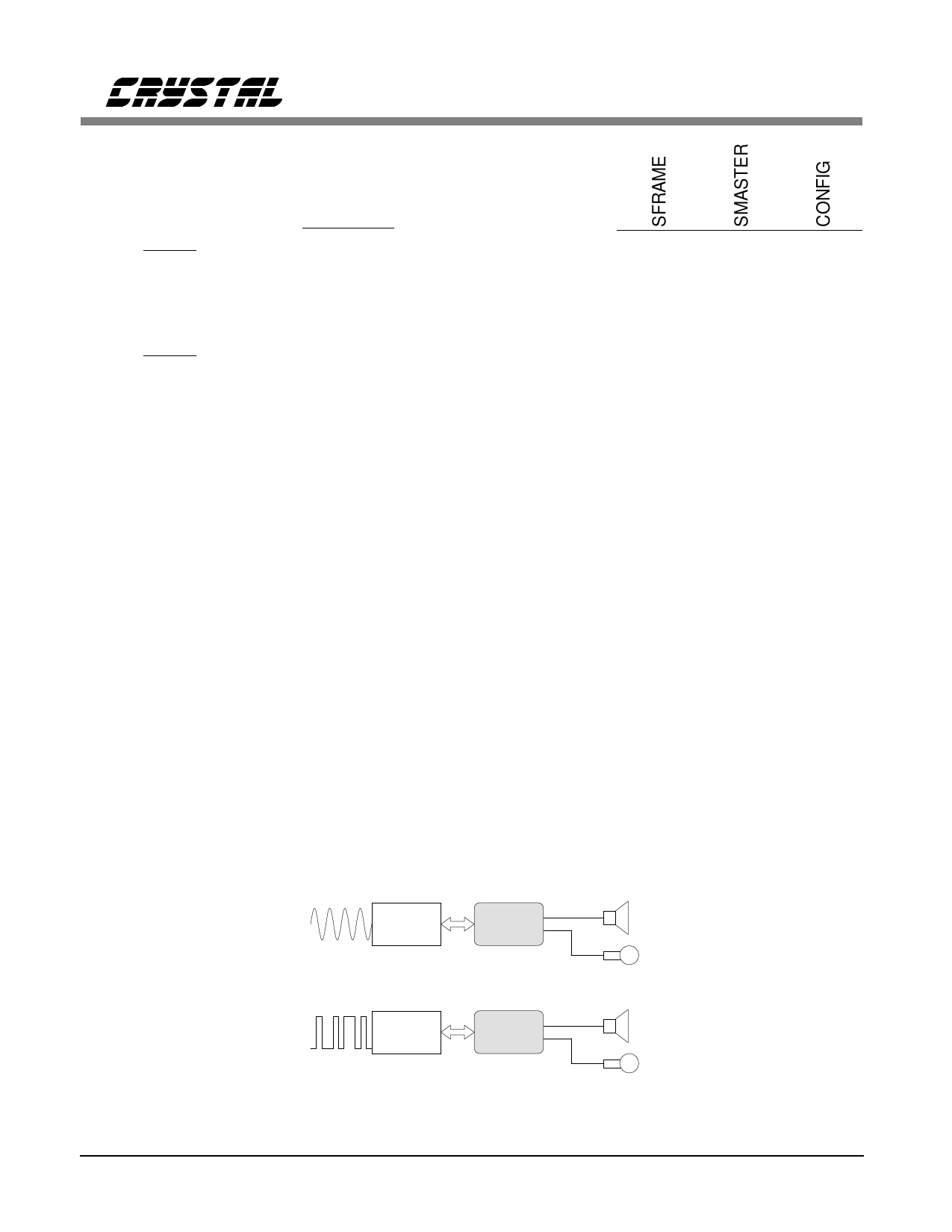
As indicated in Table 2, the CS6403 has two ba-
sic operating modes. These operating modes are
illustrated in Figure 4.
The simplest operating mode is Mode 1. This
operating mode is useful in applications where
the data link to the far end is analog, as in ana-
log cellular hands free, or in analog speaker
phones. The SSI is the system timing master in
Mode 1. Long or short framing signals can be
generated. Word length is always 8 bits.
Mode 2 is useful in applications where the data
link to the far end is digital, as in digital cellular
hands free, or in digital (ISDN) speaker phones.
The SSI is the system timing slave in Mode 2.
Only short framing pulses are accepted. Word
length can be 8 or 16 bits. Mode 2 allows ac-
cess to control registers in 16-bit Mode.
States of Operation
Reset
Reset may be asserted either by setting the RE-
SET (PIN 41Q, 3L) pin high, or by setting the
Reset bit in Synchronous Serial Interface Control
Register 0 (RST: SSI_CR0.11). The only func-
tional difference between these two operations is
that setting the RESET pin clears the RST bit.
During Reset, all chip functions are halted ex-
Codec
CS6403
Far End
Mode 1
DSP
CS6403
Near End
Mode 2
Figure 4. Operating Modes
12
DS192PP6
Share Link: 